Understanding the Basics of Injection Molded Parts Tolerances
In the realm of injection molding, tolerances play a pivotal role. Tolerance, in simple terms, refers to the allowable deviation from a specified dimension in an injection - molded part. For instance, if a part is designed to have a length of 50 mm, the tolerance might be set at ±0.1 mm, meaning the acceptable length of the part can range from 49.9 mm to 50.1 mm.
Why are tolerances important?
- Functionality: In many applications, especially in industries like automotive and aerospace, injection - molded parts need to fit precisely with other components. For example, in an automotive engine, a poorly toleranced plastic cover might not seal properly, leading to oil leaks or other malfunctions. According to a study by the Society of Plastics Engineers, over 30% of product failures in the automotive industry are related to improper tolerancing of plastic parts.
- Assembly: When multiple injection - molded parts are assembled together, tight and consistent tolerances ensure a smooth assembly process. In a consumer electronics device, if the tolerances of the plastic housing parts are off, it can be difficult to snap them together, increasing production time and costs.
- Quality and reliability: Maintaining tight tolerances is a sign of high - quality manufacturing. It reduces the likelihood of defects and ensures that the final product meets or exceeds customer expectations. A case in point is the medical device industry, where even the slightest deviation in tolerance can have life - threatening consequences.
Factors Influencing Tolerances
Material - A Key Player
The type of material used in injection molding is a fundamental factor affecting tolerances. Different plastics have different shrinkage rates. For example, according to data from the American Society for Testing and Materials (ASTM), the shrinkage rate of polyethylene (PE) can range from 1.5% - 3.5%, while that of acrylonitrile - butadiene - styrene (ABS) is typically in the range of 0.4% - 0.9%. A study by Plastics Technology magazine showed that in a production run of 10,000 injection - molded parts, when using PE, the dimensional variation due to shrinkage was much higher compared to when using ABS. This significant difference in shrinkage rates means that if a tight - tolerance part is required, the material selection becomes crucial. For parts with complex geometries, materials with lower and more consistent shrinkage rates like polycarbonate (PC) with a shrinkage rate of around 0.5% - 0.7% are often preferred.
Mold Design Elements
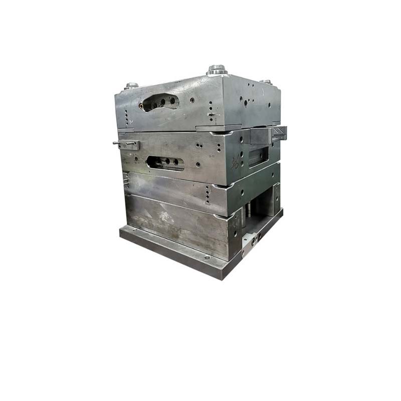
- Mold Structure: The overall structure of the mold can impact tolerances. For instance, a poorly designed mold with weak or misaligned components may cause deflection during the injection process. If the mold plates are not properly aligned, it can lead to uneven wall thicknesses in the injection - molded part. A case study by the Mold Making Technology Journal found that in molds with misaligned plates, up to 20% of the parts produced had wall - thickness variations that exceeded the tolerance limits.
- Gate Location: The position of the gate, through which the molten plastic enters the mold cavity, is vital. If the gate is located in an improper position, it can result in uneven filling of the cavity. For example, if the gate is placed too close to a thin - walled section of the part, the thicker sections may not be filled adequately, leading to dimensional inaccuracies. In a study of 500 injection - molded parts with incorrect gate locations, over 30% of the parts had significant warping issues, which affected their dimensional tolerances.
Processing Conditions
- Temperature: Both the melt temperature and the mold temperature play significant roles. If the melt temperature is too high, the plastic may degrade, and the part may shrink more during cooling. A high - temperature study by the Society of Manufacturing Engineers showed that for every 10°C increase in melt temperature above the recommended range, the shrinkage rate of the injection - molded part increased by approximately 0.1%. On the other hand, if the mold temperature is not uniform, it can cause differential cooling, leading to warping and dimensional variations.
- Pressure: Injection pressure and holding pressure are critical. High injection pressure can force the plastic into the mold cavity quickly, but it may also cause flash (excess plastic seeping into unwanted areas) if not properly controlled. Holding pressure, which is applied after the cavity is filled, helps to compensate for the shrinkage of the plastic as it cools. A study by the Plastics Industry Association found that a 10% increase in holding pressure could reduce the shrinkage of a part by about 0.05 - 0.1 mm, depending on the material.
- Time: The injection time, holding time, and cooling time all affect the final dimensions of the part. A shorter cooling time may result in a part that has not fully solidified, leading to post - molding shrinkage. For example, in a production line where the cooling time was reduced by 20%, the parts had an average dimensional increase of 0.2 - 0.3 mm due to insufficient cooling.
Tolerance Standards and Specifications
In the injection - molded parts industry, several well - recognized tolerance standards and specifications are used globally. These standards serve as guidelines for manufacturers to ensure that the parts they produce meet certain quality and dimensional accuracy requirements.
ISO Standards
The International Organization for Standardization (ISO) has a set of standards related to plastic products and tolerances. For injection - molded parts, ISO 294 - 4 focuses on the tolerances of injection - molded thermoplastic materials. This standard classifies tolerances into different grades based on the size of the part. For example, for small - sized parts (up to 3 mm in size), the general tolerance grade MT2 might have a dimensional tolerance of ±0.05 mm for linear dimensions, while for larger parts (say, 100 - 315 mm), the same tolerance grade MT2 could have a tolerance of ±0.25 mm.
ASTM Standards
The American Society for Testing and Materials (ASTM) also provides standards relevant to injection - molded parts. ASTM D4000 is a standard practice for specifying plastic materials by chemical structure, property ranges, and other characteristics. Although not strictly a tolerance - only standard, it is often used in conjunction with other ASTM standards when setting tolerances. ASTM E228 is a standard test method for coefficient of linear thermal expansion of solid materials. Since the thermal expansion of materials used in injection molding can affect tolerances, this standard helps in understanding how materials will behave during the molding and cooling processes.
Comparison of Tolerance Ranges in Different Standards
The following table provides a comparison of tolerance ranges for injection - molded parts in some common standards for a linear dimension of a part with a nominal size of 50 mm:
| Standard | Tolerance Grade | Tolerance Range (mm) |
| ISO 294 - 4 (MT3) | General tolerance for medium - precision parts | ±0.15 |
| DIN 16749 (finer tolerance class) | ±0.12 | |
| ASTM (equivalent medium - precision reference) | ±0.1 - 0.2 (approximate range depending on material and other factors) |
It's important to note that while these standards provide a framework, actual tolerances for a specific injection - molded part may need to be adjusted based on the factors mentioned earlier, such as material properties, mold design, and processing conditions. Different industries may also have their own preferred standards or may require a combination of standards to meet their unique requirements. For example, the medical device industry often adheres to strict ISO standards due to the high - risk nature of its products, while the consumer goods industry may be more flexible depending on the product's functionality and cost - effectiveness requirements.
Measuring and Controlling Tolerances
Precision Measuring Tools
Accurate measurement is the cornerstone of controlling tolerances in injection - molded parts. There are several precision measuring tools commonly used in the industry.
- Calipers: Vernier calipers and digital calipers are widely used for measuring linear dimensions. They can measure the length, width, and thickness of injection - molded parts with relatively high accuracy. For example, a high - quality digital caliper can measure dimensions with an accuracy of up to ±0.01 mm. They are especially useful for measuring the outer dimensions of simple - shaped injection - molded parts, such as the length of a plastic rod or the thickness of a flat - panel part.
- Micrometers: Micrometers offer even higher precision for measuring small dimensions. They are typically used for measuring the diameters of holes, the thickness of thin - walled sections, or the dimensions of small features on injection - molded parts. A standard micrometer can achieve an accuracy of ±0.001 mm, making it suitable for measuring parts where tight tolerances are required, like in the production of small electronic components.
- Coordinate Measuring Machines (CMMs): CMMs are highly sophisticated devices that can measure the three - dimensional coordinates of points on a part's surface. They are capable of performing complex measurements and can accurately measure the shape, position, and dimensions of injection - molded parts with complex geometries. For instance, in the automotive industry, CMMs are used to measure the dimensions of engine components made of injection - molded plastics to ensure they meet the strict tolerances required for proper engine operation. A CMM can measure with an accuracy of a few micrometers, depending on its model and calibration.
- Optical Measuring Instruments: Optical comparators and laser scanners are also important tools. Optical comparators project an enlarged image of the part onto a screen and compare it with a reference template to measure dimensions and check for shape accuracy. Laser scanners, on the other hand, can quickly capture the three - dimensional shape of a part by emitting laser beams and measuring the reflected light. They are very useful for inspecting large - scale or complex - shaped injection - molded parts, such as automotive bumpers or large - sized plastic housings.
Quality Control Measures
Implementing effective quality control measures is crucial for controlling tolerances throughout the production process.
- First - Article Inspection: This is the inspection of the first part or a small batch of parts produced after setting up a new production run, changing the mold, or making any significant process adjustments. First - article inspection helps to identify any potential issues with the mold, the injection - molding process, or the materials before full - scale production begins. For example, if the first - article inspection reveals that the dimensions of a part are outside the tolerance range, adjustments can be made to the mold, the processing parameters, or the material formulation. It is estimated that performing first - article inspection can reduce the defect rate in mass production by up to 50% by catching problems early.
- In - Process Inspection: Also known as process 巡检,in - process inspection involves regularly checking parts during the production process. Inspectors randomly select parts at various intervals (e.g., every 100 parts or every hour) to measure dimensions, check for surface defects, and ensure that the production process is still within the tolerance limits. This helps to detect any gradual changes in the process, such as mold wear or equipment drift. A study in a large - scale injection - molding factory found that implementing in - process inspection reduced the number of out - of - tolerance parts by 30% during a production run.
- Final Inspection: Before the injection - molded parts are shipped to the customer, a final inspection is carried out. This comprehensive inspection ensures that all parts meet the specified tolerances and quality standards. All critical dimensions are measured, and the parts are checked for any visual defects, functionality issues, and compliance with the relevant standards and specifications. Final inspection acts as the last line of defense to prevent defective parts from reaching the customer, protecting the company's reputation and reducing the cost of returns and rework.
Yigu Technology's Perspective
As a non - standard plastic metal products custom supplier, Yigu Technology deeply understands the significance of tight tolerance control for injection - molded parts. We always start from the material selection stage. By collaborating closely with reliable material suppliers, we ensure that the materials used have stable shrinkage rates, which is the basis for controlling tolerances.
In mold design, our experienced engineers use advanced software for simulation analysis to optimize the mold structure and gate location. This not only improves the filling quality of the plastic melt but also effectively reduces the occurrence of dimensional deviations. During the injection - molding process, we use high - precision equipment and strictly monitor processing conditions such as temperature, pressure, and time. Our quality control team conducts first - article inspections, in - process inspections, and final inspections in accordance with international standards. This multi - level inspection system allows us to promptly detect and address any tolerance - related issues, ensuring that each injection - molded part we supply meets the highest quality standards.
FAQ
What is the typical tolerance range for injection molded parts?
The typical tolerance range for injection - molded parts can vary widely depending on several factors. Generally, for standard - precision parts, the tolerance can be in the range of ±0.1 - 0.5 mm. For example, in consumer goods like plastic toys, a tolerance of ±0.3 mm might be acceptable for many dimensions. However, for high - precision applications such as aerospace components or medical devices, tolerances can be as tight as ±0.01 - 0.05 mm. Material properties play a significant role; materials with high shrinkage rates will have a broader tolerance range. Also, the size of the part matters - larger parts usually have relatively wider tolerances compared to smaller ones.
How can I reduce tolerances in injection molding?
To reduce tolerances in injection molding, start with proper material selection. Choose materials with low and consistent shrinkage rates. For example, engineering plastics like polycarbonate (PC) are often a good choice for parts requiring tight tolerances. Optimize the mold design, ensuring proper alignment of mold components and an appropriate gate location. Use high - precision molds with well - finished surfaces. During the injection - molding process, closely control processing conditions such as temperature, pressure, and time. Implement a comprehensive quality control system, including first - article inspection, in - process inspection, and final inspection, to catch and correct any dimensional issues early.
Can tight tolerances affect the cost of injection molded parts?
Yes, tight tolerances can significantly affect the cost of injection - molded parts. Tighter tolerances require more precise molds, which are often more expensive to design and manufacture. High - precision molds may need to be made from more expensive materials and require advanced machining techniques. The injection - molding process also becomes more challenging to control when aiming for tight tolerances. This may involve using more sophisticated equipment and more frequent quality checks, increasing production time and labor costs. For example, if a part's tolerance is tightened from ±0.2 mm to ±0.05 mm, the cost of the part can increase by 30 - 50% due to the additional requirements in mold making and production control.


