What is Boss Injection Molding?
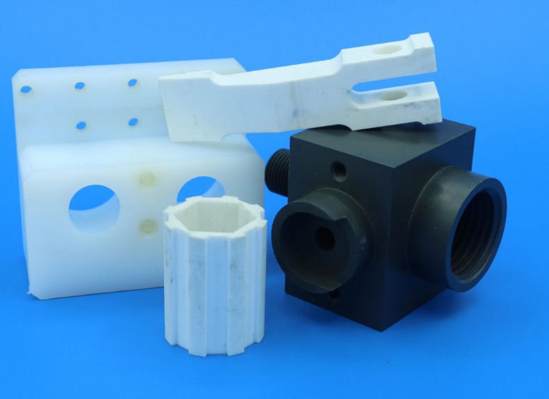
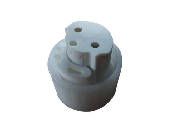
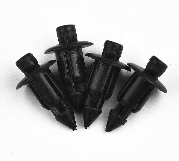
Boss injection molding is a specialized application within the broader field of injection molding, a manufacturing process renowned for its efficiency in mass - producing plastic parts. In boss injection molding, the focus is on creating plastic components with one or more bosses. A boss, in the context of plastic parts, is a small, typically cylindrical or round protrusion that extends from the surface of the main plastic body.
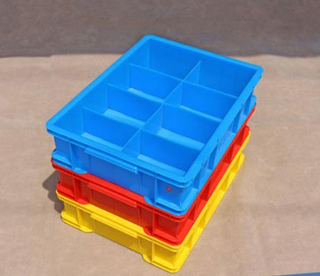
These bosses serve several crucial functions. One of the primary roles is for structural reinforcement. For example, in large plastic enclosures, bosses can be strategically placed at key stress points. Let's say in a computer server housing, bosses are added around the areas where internal components are mounted. By doing so, they distribute the weight and stress more evenly across the plastic structure, preventing it from warping or cracking under the load of the internal hardware. This is especially important as plastic, while lightweight and versatile, can be prone to deformation if not properly reinforced in high - stress areas.
Another significant function of bosses is for connection purposes. They act as attachment points, allowing for the easy assembly of multiple parts. In the automotive industry, plastic interior components often use bosses to connect to other parts of the vehicle's interior structure. For instance, a plastic dashboard panel may have bosses that align with corresponding holes in the vehicle's frame. Fasteners such as screws or bolts can then be inserted through these bosses to secure the dashboard panel firmly in place. This makes the assembly process more straightforward and efficient, reducing the time and effort required for manufacturing.
In some cases, bosses are also used for alignment. They ensure that parts are correctly positioned relative to each other during assembly. Consider a multi - part plastic toy construction set. Each piece may have bosses that fit precisely into corresponding sockets on other pieces. This not only helps in the proper alignment of the parts but also enhances the overall stability of the assembled toy. Without these alignment - enabling bosses, the toy may be wobbly or not function as intended.
The Working Mechanism of Boss Injection Molding
Plastic Material Preparation
The first step in boss injection molding is the preparation of the plastic material. Usually, plastic in the form of granules or powder is loaded into the hopper of the injection - molding machine. The choice of plastic material is crucial as different plastics have distinct properties. For example, polyethylene (PE) is known for its good chemical resistance and flexibility, while polypropylene (PP) offers higher heat resistance and stiffness. These characteristics directly impact the final properties of the boss - containing plastic part. The moisture content of the plastic raw material also needs to be carefully monitored. High - moisture plastics, when melted, can cause defects such as bubbles in the final product. Therefore, some plastics may require pre - drying before being loaded into the hopper.
Heating and Melting
Once in the hopper, the plastic material is pushed forward by a screw or a plunger into the heating zone of the injection - molding machine. As it moves through the heating channels, the plastic is gradually heated until it reaches its melting point and turns into a molten state. Temperature control during this stage is of utmost importance. Each type of plastic has a specific melting range. For instance, the melting temperature of ABS plastic typically ranges from 200 - 250°C. If the temperature is set too low, the plastic may not melt completely, leading to uneven flow during injection and resulting in defects like short - shots (incomplete filling of the mold). On the other hand, if the temperature is too high, the plastic may degrade, losing its mechanical properties and potentially causing discoloration or charring.
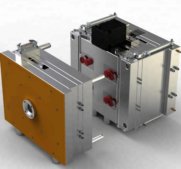
Injection into the Mold
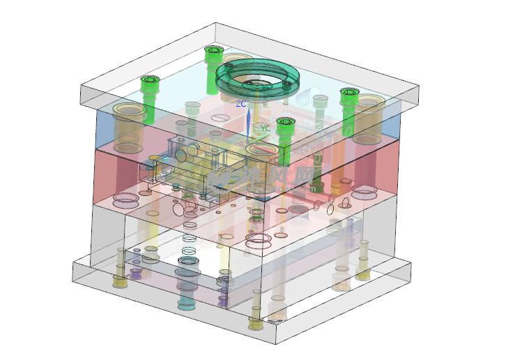
The molten plastic, now in a highly fluid state, is then injected into the mold under high pressure. The mold is specifically designed with a cavity that includes the shape of the desired plastic part along with the bosses. The pressure during injection can range from several hundred to several thousand pounds per square inch (psi), depending on factors such as the complexity of the mold, the viscosity of the molten plastic, and the size of the part. The flow of the molten plastic into the mold is a critical aspect. The mold design must ensure that the plastic reaches all parts of the cavity, including the narrow and detailed areas of the bosses, without any air pockets or voids. A well - designed runner and gate system in the mold helps to direct the flow of the molten plastic efficiently. For example, a pinpoint gate may be used for small and precise bosses to ensure accurate filling.
Cooling and Solidification
After the mold is filled with the molten plastic, the cooling process begins. Cooling is essential as it allows the plastic to solidify and take the shape of the mold cavity, including the bosses. The cooling time can vary significantly depending on the thickness of the part, the type of plastic, and the cooling system used. During this stage, the temperature of the mold plays a crucial role. A lower mold temperature generally leads to faster cooling. However, if the cooling is too rapid, it can cause internal stresses in the plastic part, resulting in warping, cracking, or dimensional inaccuracies. For example, in the case of thick - walled plastic parts with large bosses, a slower and more controlled cooling rate may be required to ensure uniform solidification.
Mold Opening and Part Ejection
Once the plastic has cooled and solidified sufficiently, the mold is opened. This is usually achieved by the action of the injection - molding machine's hydraulic or mechanical systems. The two halves of the mold (the stationary and the moving half) are separated. After the mold is open, the 成型制品 (the plastic part with the bosses) needs to be removed from the mold. This is accomplished using an ejection system. The ejection system typically consists of ejector pins, which are strategically placed in the mold. When activated, these pins push against the plastic part, forcing it out of the mold cavity. The design of the ejection system is important to ensure that the part is ejected smoothly without causing any damage. For example, the ejector pins should be located in areas where the plastic part has sufficient strength to withstand the ejection force, such as near the bosses or on thick - walled sections of the part.
Post - processing
In many cases, the molded plastic part with bosses may require post - processing steps to achieve the final product quality. One common post - processing step is the removal of flash, which is the excess plastic that may have seeped into the small gaps between the mold halves during injection. Flash can be removed manually using tools like knives or by mechanical means such as tumbling. Trimming may also be necessary to cut off any excess material or to refine the edges of the part. In some instances, the part may need to be painted or coated for aesthetic or functional reasons. For example, a plastic part with bosses that will be used in an electronic device may be painted to match the color scheme of the device or coated with a protective layer to enhance its durability and resistance to environmental factors.
Applications of Boss Injection Molding
Boss injection molding finds extensive applications across various industries due to its ability to produce high - quality plastic parts with specific functional features. Here are some of the key application areas:
Consumer Electronics
In the consumer electronics industry, boss injection molding is widely used. For example, in the production of mobile phone cases, bosses are crucial for several reasons. They provide attachment points for internal components such as the battery holder, circuit board mounts, and camera modules. A typical mid - range smartphone case may have around 10 - 15 bosses of different sizes and shapes. These bosses ensure that the internal components are securely fixed in place, preventing them from shifting during normal use or when the phone is dropped. In the case of laptop keyboards, bosses are used to attach the keycaps to the underlying membrane or circuit board. Each keycap is usually connected to the base through a small boss, and a standard laptop keyboard can have over 100 such connection points. This not only ensures proper key function but also provides stability and durability to the keyboard.
Automotive Industry
The automotive industry heavily relies on boss injection molding. Dashboard components, which are complex plastic parts, use bosses for multiple purposes. They are used to attach various sub - components like air vents, instrument clusters, and control panels. A modern car dashboard may have dozens of bosses. For instance, the air vents in a car dashboard are often attached to the main dashboard structure through bosses. This allows for easy installation and replacement if needed. Headlight housings also benefit from boss injection molding. The bosses in a headlight housing can be used to attach the lens, the bulb holder, and the mounting brackets to the vehicle's frame. This ensures that the headlight is properly aligned and securely mounted, providing optimal illumination on the road.
Medical Equipment
In the medical field, precision and reliability are of utmost importance, and boss injection molding meets these requirements. Syringes, a common medical device, often have bosses. The plunger of a syringe is attached to the barrel through a boss - like structure. This connection must be precise to ensure smooth operation and accurate dosage delivery. For example, in a 10 - mL syringe, the boss - based connection between the plunger and the barrel allows for consistent and controlled pushing of the plunger, which is crucial for administering medications accurately. Medical instrument housings, such as those for blood glucose monitors or ultrasound devices, also use bosses. These bosses are used to attach internal electronic components, sensors, and display screens. The tight tolerances achievable with boss injection molding ensure that the sensitive internal components are well - protected and properly aligned, maintaining the accuracy and functionality of the medical device.
Daily Necessities
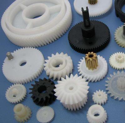
Plastic bottle caps, a ubiquitous item in daily life, are often produced using boss injection molding. The bosses in a bottle cap can be used to attach the inner seal or to provide a better grip for opening and closing. For example, in a standard 500 - mL water bottle cap, there may be small bosses on the inner side that help in securing the seal, preventing leakage. Kitchen utensils like plastic spatulas or ladles may have bosses to attach handles. A typical plastic spatula handle is attached to the main body through one or two bosses, providing a strong and stable connection. In the toy industry, boss injection molding is used to create various parts of toys. For example, in a construction - style toy set, the individual plastic bricks may have bosses on their sides and tops. These bosses allow the bricks to be easily connected to each other, enabling children to build different structures. A small - sized construction toy set may have hundreds of bricks, each with multiple bosses, providing endless creative possibilities for kids.
Yigu Technology's View
As a non - standard plastic metal products custom Supplier, Yigu Technology highly values boss injection molding. With years of experience in the field, we have mastered the art of creating custom - designed plastic parts with bosses that meet the diverse needs of our clients.
Our expertise lies in handling complex design requirements. Whether it's a unique boss shape or a specific arrangement on the plastic body, we have the technical know - how to bring these designs to life. We understand that each industry has its own set of challenges, and our team of experts works closely with clients to ensure that the boss - injection - molded parts not only meet but exceed their expectations.
Quality is at the core of our operations. We use high - grade plastic materials and state - of - the - art injection - molding equipment. Our strict quality control process ensures that every part leaving our factory is free from defects and has consistent dimensional accuracy. This commitment to quality has earned us the trust of clients across various industries, from consumer electronics to medical equipment manufacturers.
FAQs about Boss Injection Molding
What types of plastics are most suitable for Boss Injection Molding?
Several types of plastics are well - suited for boss injection molding, each with its own set of advantages. Acrylonitrile Butadiene Styrene (ABS) is a popular choice. It offers a good balance of strength, impact resistance, and dimensional stability. For example, in the production of electronic device housings, ABS can withstand the mechanical stress associated with the attachment of components through bosses without cracking or deforming easily. Its melting temperature range of 200 - 250°C makes it relatively easy to process in injection - molding machines.
Polypropylene (PP) is another suitable plastic. It has excellent chemical resistance, which is beneficial when the boss - containing parts may be exposed to various substances. In automotive applications, such as interior trim components with bosses for attachment, PP's resistance to oils and detergents used in vehicle maintenance is a major advantage. PP also has a relatively high melting point around 160 - 170°C, allowing it to maintain its shape well under normal operating temperatures.
Polycarbonate (PC) is known for its high impact strength, heat resistance, and optical clarity. In applications where the boss - containing parts need to be both strong and transparent, like in some medical device housings or lighting fixtures, PC is an ideal choice. Its melting temperature typically ranges from 260 - 340°C, and careful temperature control is required during the injection - molding process to ensure proper flow and quality of the final product.
How can we ensure the quality of boss - shaped parts in injection molding?
To ensure the quality of boss - shaped parts in injection molding, several factors need to be carefully controlled. Temperature control is crucial. The melt temperature of the plastic should be maintained within the appropriate range for the specific plastic being used. For instance, if the melt temperature is too low, the plastic may not flow smoothly into the mold cavity, especially in the narrow areas of the bosses, leading to incomplete filling or poor surface finish. On the other hand, if it's too high, the plastic may degrade, losing its mechanical properties.
Pressure management is also essential. The injection pressure must be sufficient to fill the mold cavity completely, including the details of the bosses. However, excessive pressure can cause problems such as flash (excess plastic in thin layers around the part) or damage to the mold. During the holding pressure stage, the right amount of pressure should be applied to compensate for the shrinkage of the plastic as it cools, ensuring dimensional accuracy of the bosses.
Mold design optimization plays a significant role. The mold should have proper venting to allow the escape of air during injection. Without adequate venting, air pockets can form inside the bosses, weakening the structure. The gate location, which is the point where the molten plastic enters the mold, should be carefully selected. A well - placed gate can ensure uniform flow of the plastic into the bosses, preventing issues like weld lines or uneven filling. Additionally, the mold's cooling channels should be designed to provide uniform cooling, minimizing internal stresses that could lead to warping or cracking of the boss - shaped parts.