Understanding Injection Molding Basics
What is Injection Molding?
Injection Molding, a widely used manufacturing process, involves injecting molten material into a mold cavity under high pressure. Once inside the mold, the material cools and solidifies, taking on the precise shape of the mold cavity. After solidification, the finished part is ejected from the mold. This process isn't limited to plastics; it can also be applied to materials like metal (in the form of metal powder injection molding) and rubber. For instance, in the automotive industry, many plastic components such as dashboards, bumpers, and interior trims are produced through injection molding. In the medical field, precision plastic parts like syringes and medical device components are also made using this method.
Key Components in the Injection Molding Setup
- Injection Machine
- Hopper: This is where the raw material, usually in pellet form, is initially loaded. It serves as a storage bin that feeds the material into the barrel at a controlled rate. For example, in a typical plastic injection molding process, plastic pellets are poured into the hopper.
- Screw: The screw is a crucial part within the barrel. It rotates to convey the raw material forward, while also melting and homogenizing it. As the screw rotates, it generates heat through friction, which helps in melting the plastic pellets.
- Heating Unit: Surrounding the barrel, the heating unit ensures that the material reaches the appropriate melting temperature. Different materials have different melting points. For example, polyethylene (PE) has a melting point in the range of 110 - 130°C, while polycarbonate (PC) melts at around 220 - 230°C. The heating unit needs to be precisely controlled to match these requirements.
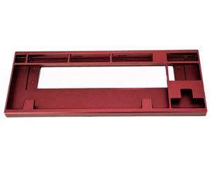
- Mold
- Stationary Mold Half (Fixed Mold): This part of the mold is attached to the injection machine's stationary platen. It typically contains the cavity into which the molten material is injected.
- Moving Mold Half: Attached to the moving platen of the injection machine, it moves during the injection molding cycle to close and open the mold. When the mold is closed, it forms a complete cavity with the stationary half.
- Cavity: The cavity is the hollow space within the mold that gives the final part its shape. The design of the cavity is a direct representation of the part to be produced. For example, if you're making a plastic toy, the cavity will be shaped like that toy.
- Core: In some cases, a core is used to create internal features or holes in the part. It is placed inside the cavity, and the molten material flows around it. For instance, when making a plastic pipe fitting with an internal hole, a core is used to form that hole.
Here is a summary table of the key components and their functions:
| Component | Function |
| Hopper | Stores and feeds raw material into the barrel |
| Screw | Conveys, melts, and homogenizes the raw material |
| Heating Unit | Melts the raw material by providing heat |
| Stationary Mold Half | Holds the cavity and is fixed to the stationary platen |
| Moving Mold Half | Moves to close and open the mold, and forms the cavity with the stationary half when closed |
| Cavity | Determines the external shape of the final part |
| Core | Creates internal features or holes in the part |
Step - by - Step Process of Crafting Parts for Injection Molding
Step 1: Material Selection
Material selection is a crucial first step in injection molding. When choosing a material, several factors come into play. The product's end - use environment is vital. For example, if a part will be exposed to high temperatures, a material with high heat resistance like polycarbonate (PC) is preferred. PC has a heat deflection temperature of around 130 - 140°C (at 1.82 MPa load), making it suitable for applications such as automotive lighting components that can get hot during operation.
Physical property requirements also matter. Tensile strength is important for parts that need to withstand pulling forces. Polypropylene (PP) has a tensile strength in the range of 30 - 40 MPa, which makes it useful for products like plastic containers that need to maintain their shape under normal handling. Cost is another significant factor. Polystyrene (PS), with a relatively low cost, is often used for disposable items like plastic cutlery.
Here is a comparison of some common injection - molding materials:
| Material | Melting Point (°C) | Tensile Strength (MPa) | Density (g/cm³) | Cost (Relative) |
| Polyethylene (PE) - Low - Density (LDPE) | 105 - 115 | 7 - 15 | 0.91 - 0.94 | Low |
| Polyethylene (PE) - High - Density (HDPE) | 125 - 135 | 20 - 35 | 0.94 - 0.97 | Low - Medium |
| Polypropylene (PP) | 160 - 170 | 30 - 40 | 0.90 - 0.91 | Medium |
| Polystyrene (PS) | 100 - 110 | 35 - 60 | 1.04 - 1.06 | Low |
| Polycarbonate (PC) | 220 - 230 | 60 - 70 | 1.20 | High |
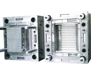
Step 2: Mold Design and Preparation
Mold design is the heart of the injection - molding process. A well - designed mold ensures high - quality parts with accurate dimensions and good surface finish.
The mold structure design involves several key elements. The parting line is the boundary where the two halves of the mold separate. It should be carefully chosen to ensure easy part ejection and minimize visible seams on the part. For example, in the design of a plastic bottle mold, the parting line is often located around the circumference of the bottle, allowing for smooth removal of the molded bottle.
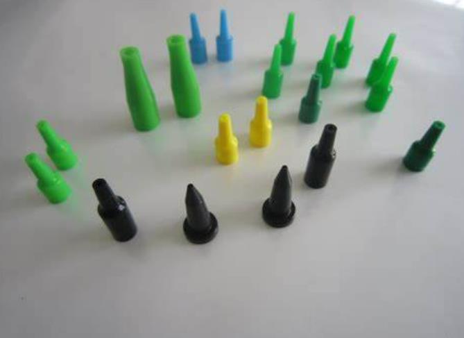
The gate is the opening through which the molten material enters the mold cavity. Different types of gates, such as pin gates, edge gates, and film gates, are used depending on the part's shape and requirements. A pin gate is often used for small, precise parts as it provides a small, clean entry point for the plastic.
The runner system, which includes the main runner and sub - runners, distributes the molten material from the injection nozzle to the gates. It should be designed to minimize pressure loss and ensure uniform filling of the cavities.
The mold - design process typically follows this flowchart:
| Step | Description |
| 1. Product Analysis | Examine the part's 3D model, consider its dimensions, tolerances, and features. |
| 2. DFM (Design for Manufacturing) | Evaluate the part's manufacturability, suggest design improvements if needed. |
| 3. Parting Line Determination | Decide on the location of the parting line. |
| 4. Gate and Runner Design | Design the gate type, size, and runner layout. |
| 5. Cooling System Design | Plan the cooling channels to ensure even cooling. |
| 6. Ejection System Design | Design the ejection mechanism to remove the part from the mold. |
| 7. Mold Assembly Design | Design how the mold components will be assembled. |
During mold processing, high - precision machining techniques like CNC (Computer Numerical Control) milling and EDM (Electrical Discharge Machining) are often used. CNC milling can achieve tight tolerances, typically within ±0.05 mm, while EDM is useful for creating complex shapes and fine details. Assembly of the mold requires careful alignment of components to ensure proper function. Bolts and dowel pins are commonly used to hold the mold parts together, and the alignment should be within ±0.02 mm for optimal performance.
Step 3: Machine Setup and Calibration
Proper machine setup and calibration are essential for consistent and high - quality injection - molded parts.
Temperature settings are critical. The barrel of the injection machine is divided into multiple zones, each with its own temperature control. For example, when processing ABS, the rear zone of the barrel might be set at around 170 - 180°C, the middle zone at 190 - 200°C, and the front zone (near the nozzle) at 210 - 220°C. The mold temperature also affects the part's quality. For a thin - walled plastic part, a lower mold temperature of around 40 - 50°C might be used to promote quick cooling and reduce cycle time.
Pressure settings include injection pressure and 保压压力. Injection pressure is used to force the molten material into the mold cavity. For a complex - shaped part with long flow paths, a higher injection pressure of 100 - 150 MPa might be required. 保压压力,which is applied after the cavity is filled, helps to compensate for material shrinkage during cooling. A 保压压力 of 30 - 50 MPa is commonly used.
The injection speed, which is the rate at which the screw moves forward to inject the molten material, also impacts the part quality. A high injection speed can cause air traps and flow marks, while a low injection speed might lead to incomplete filling. For a medium - sized part, an injection speed of 30 - 60 mm/s could be appropriate.
Here is a table showing how different parameters affect product quality:
| Parameter | High Setting Effect | Low Setting Effect |
| Temperature | Risk of material degradation, over - heating of the part | Incomplete melting, poor flow, short shots |
| Injection Pressure | Flash (excess material at the mold seams), high internal stresses | Incomplete filling, weak weld lines |
| Injection Speed | Air traps, flow marks | Incomplete filling, long cycle times |
Step 4: Injection and Filling
Once the machine is set up, the injection and filling process begins. The molten material, which has been heated and plasticized in the barrel, is forced through the nozzle, runner system, and gates into the mold cavity.
As the plastic enters the cavity, it flows in a specific pattern. In a simple rectangular - shaped cavity, the plastic might flow from the gate in a front - advancing wave - like pattern. However, in complex - shaped cavities with multiple features and thin - walled sections, the flow can be more intricate.
Pressure maintenance and contraction is an important concept during this stage. After the cavity is filled, the material starts to cool and shrink. Pressure holding pressure is applied to push additional material into the cavity to compensate for this shrinkage. This helps to ensure that the part has the correct dimensions and density. If Pressure holding is not applied properly, the part may have sink marks or be under - filled in some areas.
Step 5: Cooling and Solidification
Cooling is a crucial stage as it determines the part's dimensional stability and production cycle time. The cooling time can be calculated using the formula \(t = \frac{h^{2}}{4\alpha}\), where \(t\) is the cooling time, \(h\) is the thickness of the part, and \(\alpha\) is the thermal diffusivity of the material. For example, for a 3 - mm - thick part made of PP (with a thermal diffusivity of approximately \(1.1\times10^{-7} m^{2}/s\)), the cooling time can be estimated.
Factors that affect the cooling time include the part's thickness, the mold material (a copper - alloy mold with high thermal conductivity will cool the part faster than a steel mold), and the coolant temperature. If the cooling is not uniform, it can lead to product defects such as Warping and deformation. For instance, if one side of a part cools much faster than the other, the part will warp towards the cooler side.
To optimize the cooling system, several strategies can be employed. Using baffles in the cooling channels can improve the coolant flow and heat transfer efficiency. Also, ensuring that the cooling channels are evenly distributed around the mold cavity helps to achieve uniform cooling.
Step 6: Ejection and Part Removal
After the part has cooled and solidified, it needs to be ejected from the mold. The 顶出装置 in the mold is responsible for this task.
Common types of ejection devices include ejector pins which are small pins that push the part out of the mold cavity, and ejector plates, which moves the entire set of The top pin simultaneously. The top pin are usually placed in areas where they will not cause damage to the part, such as in thick - walled sections or on the non - visible surface of the part.
During the ejection process, it's important to avoid damaging the part. The ejection force should be carefully controlled. If the force is too high, it can cause the part to crack or break. Additionally, the ejection sequence should be designed to ensure that the part is evenly pushed out of the mold.
Step 7: Post - processing
Post - processing is often required to achieve the final desired appearance and functionality of the part.
Common post-processing techniques include deburring which can be done manually with tools like files or by using chemical or abrasive methods. trimming might involve trimming excess material or removing small imperfections.
Surface treatment is another important aspect. Painting can enhance the part's appearance and provide protection against corrosion. For example, a plastic automotive part might be painted to match the vehicle's color. Electroplating can give the part a metallic finish and improve its wear resistance. Print can be used to add labels, logos, or other markings to the part.
Yigu Technology's Perspective
As a non - standard plastic metal products custom Supplier, Yigu Technology has rich experience in the injection molding field. We have advanced mold design capabilities, with a team of experienced engineers who can create highly customized molds according to clients' specific requirements. Our strict quality control system ensures that every part meets the highest quality standards. From raw material inspection to the final product, we conduct multiple - step quality checks.
We offer a wide range of material options, including various plastics and metal - powder materials for metal injection molding. This allows our clients to choose the most suitable material for their products. Additionally, we are proficient in diverse processing techniques, such as precision CNC machining for mold manufacturing. Yigu Technology can provide a one - stop solution from product design to mass production, satisfying clients' personalized needs efficiently and effectively.
FAQ about Injection Molding
Q1: What's the difference between injection molding and plastic injection molding?
Injection Molding is a broad term that encompasses the process of injecting molten material, which can be plastic, metal (in metal injection molding), rubber, etc., into a mold cavity under high pressure for shaping. Plastic Injection Molding, on the other hand, is a subset of injection molding that specifically deals with plastic materials. In everyday usage, especially in the plastics manufacturing industry, the two terms are often used interchangeably. But technically, injection molding has a wider scope, while plastic injection molding is focused on the use of plastic materials in the injection - molding process.
Q2: How to choose the right plastic material for injection molding?
When choosing a plastic material for injection molding, several factors need to be considered. First, the product's performance requirements are crucial. If the part needs high strength, materials like polycarbonate (PC) or acrylonitrile - butadiene - styrene (ABS) might be suitable. PC has high impact strength, and ABS offers a good balance of strength, toughness, and heat resistance. For parts that require flexibility, thermoplastic elastomers (TPEs) can be a great choice.
The processing performance of the material also matters. Materials with good flowability are easier to inject into the mold cavity. For example, polyethylene (PE) has relatively good flowability, which makes it suitable for complex - shaped parts. Cost is another significant factor. Commodity plastics like PE and PP are generally more cost - effective and are often used for large - scale production of everyday items, while engineering plastics such as PC and polyetheretherketone (PEEK) are more expensive and are typically reserved for applications where high - performance requirements outweigh cost concerns.