SOLIDWORKS Plastics transcends the simplistic notion of "simulation software." It's a sophisticated, integrated design and analysis environment that empowers engineers to navigate the complex interplay of material science, thermodynamics, and structural mechanics inherent in plastic part and injection mold design. Forget linear workflows; SOLIDWORKS Plastics fosters a dynamic, iterative process where design modifications are seamlessly integrated with real-time analysis, enabling predictive optimization of form, fit, and function with unprecedented precision.
The software's power lies not merely in its capacity to import CAD models, but in its ability to harness them as the foundation for intricate simulations. The user isn't passively observing; they're actively manipulating parameters – injection speed, pressure profiles, melt temperature, cooling channel geometry – to probe the highly non-linear behavior of molten polymers within the mold cavity. This isn't about simply "seeing" the fill; it's about predicting weld lines, sink marks, warpage, and residual stresses with a level of accuracy that directly impacts manufacturability and product longevity.
Finite Element Analysis (FEA) within SOLIDWORKS Plastics moves beyond rudimentary stress assessments. It allows for the detailed examination of complex stress states, accounting for anisotropic material properties, non-linear viscoelastic behavior, and the influence of residual stresses induced during the molding process. This predictive capability enables engineers to proactively address potential failure points, optimizing part geometry to withstand anticipated loading conditions and extending product lifespan.
Beyond analysis, SOLIDWORKS Plastics provides a robust suite of parametric modeling tools, facilitating the rapid prototyping and iterative refinement of both parts and molds. The software's capacity to seamlessly integrate design modifications with subsequent simulations accelerates the design cycle, enabling engineers to explore a wider design space and converge on optimal solutions with significantly reduced lead times. Furthermore, its comprehensive import/export functionality ensures seamless collaboration across different CAD platforms, fostering efficient workflows within larger engineering teams.
In conclusion, SOLIDWORKS Plastics is not merely a tool; it's a strategic asset for organizations seeking to optimize the design and manufacturing of plastic parts. Its predictive capabilities, coupled with its intuitive design environment, empower engineers to move beyond reactive problem-solving and embrace a proactive, data-driven approach to product development, resulting in superior product quality, reduced manufacturing costs, and accelerated time-to-market. The mastery of this software translates directly into a competitive advantage in today's demanding marketplace.
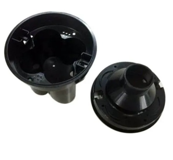
What is Plastic Injection Molding?
here's the thing about plastic injection molding: it's like this cool way to make stuff. You see, they take hot, melted plastic and shoot it into a metal mold. Then, the plastic chills out and hardens into the shape they want. It's pretty nifty, actually.
The mold itself is split into two parts - one that stays put and another that can move. And guess what? Inside the mold, there are little channels and paths that help guide the plastic where it needs to go, and even let air escape so the final product doesn't have any annoying bubbles.
Now, why do we care about this process? Well, because it's used to make tons of things we use every day. Like car parts, medical gadgets, our favorite electronic toys, and even the packaging for our snacks. It's super handy because you can whip up loads of items quickly, without needing a ton of people working on them. Plus, you can get really creative with the designs, and everything comes out just the right size.
Benefits of SOLIDWORKS Plastics for Product Development
The integration of SOLIDWORKS Plastics in your workflows provides several benefits when you develop plastic parts and molds. With SOLIDWORKS Plastics, you can:
- Predict and avoid manufacturing defects in plastic parts and injection molds, such as short shots, weld lines, sink marks, air traps, and warpage.
- Evaluate part manufacturability while you design, reducing costly rework and improving part quality.
- Optimize mold design and process settings to minimize cycle time and maximize efficiency.
- Validate different material choices and part configurations with ease.
- Leverage the SOLIDWORKS user interface and data integrity for ease of use and data reuse.
Capabilities of SOLIDWORKS Plastics
SOLIDWORKS Plastics is offered in three product bundles: SOLIDWORKS Plastics Standard, SOLIDWORKS Plastics Professional, and SOLIDWORKS Plastics Premium. Each bundle provides different capabilities to suit your needs.
- SOLIDWORKS Plastics Standard: This bundle allows you to ensure part manufacturability during the design process. You can analyze how melted plastic flows during the injection molding process to predict manufacturing-related defects. You can also evaluate the final shape of the ejected part due to flow-induced and thermal stresses.
- SOLIDWORKS Plastics Professional: This bundle builds upon SOLIDWORKS Plastics Standard to analyze mold designs. You can quickly analyze single-and multi-cavity, and family mold layouts including sprues, runners, and gates. You can also estimate cycle time and optimize feed system design.
- SOLIDWORKS Plastics Premium: This bundle includes SOLIDWORKS Plastics Professional with advanced simulation functionality to analyze mold cooling line layouts and part warpage. You can optimize cooling line design to minimize cycle time and decrease manufacturing costs.
Designing the Injection Molding Process
The injection molding design process typically consists of two phases: Definition and Validation.
Definition Phase
During the Definition phase, you define the proper process settings and validate the runner system design. These settings depend on the selected material and the part’s thickness distribution. Typical settings include:
- Injection pressure: The pressure applied by the injection unit to push the molten plastic into the mold cavity.
- Injection time: The time required to fill the mold cavity with plastic material.
- Packing pressure: The pressure applied by the injection unit to pack more material into the mold cavity after filling.
- Packing time: The time required to pack more material into the mold cavity after filling.
- Cooling time: The time required for the plastic material to cool down and solidify in the mold cavity.
- Mold temperature: The temperature of the mold surface that affects the cooling rate of the plastic material.
You can use SOLIDWORKS Plastics to perform a Flow analysis to simulate how melted plastic flows during the filling phase. You can also perform a Pack analysis to simulate how the plastic material is packed during the packing phase. These analyses help you to predict and avoid potential defects, such as short shots, weld lines, air traps, and sink marks. You can also use SOLIDWORKS Plastics to evaluate the runner system design and optimize the sprue, runner, and gate sizes and locations.
Validation Phase
During the Validation phase, you validate the cooling system design and evaluate the part warpage. The cooling system design affects the cycle time and the part quality. A good cooling system design should provide uniform cooling throughout the mold cavity and avoid hot spots that can cause uneven shrinkage and warpage.
You can use SOLIDWORKS Plastics to perform a Cool analysis to simulate how the plastic material cools down and solidifies in the mold cavity. You can also perform a Warp analysis to simulate how the plastic part deforms due to flow-induced and thermal stresses after ejection. These analyses help you to optimize the cooling line layout and minimize the part warpage.
Designing the Part Geometry
The part geometry is one of the most important factors that affect the injection molding process and the part quality. A good part design should consider the following aspects:
- Wall thickness: The wall thickness should be uniform as much as possible to avoid differential shrinkage and warpage. The wall thickness should also be within the recommended range for the selected material and process.
- Draft angle: The draft angle is the angle of inclination of the part surface relative to the mold opening direction. The draft angle helps to facilitate the part ejection from the mold and avoid damage to the part or mold. The draft angle should be sufficient for the part geometry and surface finish.
- Ribs and bosses: Ribs and bosses are features that provide structural support and attachment points for the part. Ribs and bosses should have a smaller wall thickness than the main wall to avoid sink marks. Ribs and bosses should also have proper draft angles and radii to avoid stress concentration and ejection problems.
- Undercuts: Undercuts are features that prevent the part from being ejected from the mold in a straight line. Undercuts should be avoided as much as possible because they require complex mold mechanisms or additional operations to remove them. If undercuts are unavoidable, they should be minimized and located in areas that do not affect the part function or appearance.
- Fillets and radii: Fillets and radii are features that smooth out sharp corners and edges on the part. Fillets and radii help to reduce stress concentration, improve material flow, enhance part strength, and improve part appearance. Fillets and radii should be applied generously to all internal and external corners and edges.
You can use SOLIDWORKS Plastics to perform a Design Advisor analysis to check your part geometry for potential manufacturability issues. You can also use SOLIDWORKS Plastics to perform a Thickness Advisor analysis to check your part thickness distribution and identify thick or thin areas.
Designing the Mold Geometry
The mold geometry is another important factor that affects the injection molding process and the part quality. A good mold design should consider the following aspects:
- Parting line: The parting line is the line where the two mold halves meet. The parting line should be located in areas that do not affect the part function or appearance. The parting line should also be smooth and continuous to avoid flash or mismatch defects.
- Ejector pins: Ejector pins are features that push the part out of the mold cavity after cooling. Ejector pins should be located in areas that do not affect the part function or appearance. Ejector pins should also have proper size, shape, number, and distribution to provide uniform ejection force and avoid deformation or damage to the part or mold.
- Runner system: The runner system is a network of channels that connects the injection unit to the mold cavity. The runner system consists of a sprue, a main runner, sub-runners, and gates. The runner system should be designed to provide balanced and efficient material flow, minimize pressure loss, reduce cycle time, and avoid defects such as jetting, hesitation, or cold slugs.
- Cooling system: The cooling system is a network of channels that circulates coolant fluid through the mold cavity. The cooling system consists of cooling lines, connectors, fittings, pumps, valves, sensors, etc. The cooling system should be designed to provide uniform and sufficient cooling throughout the mold cavity, minimize cycle time, reduce energy consumption, and avoid defects such as warpage or dimensional instability.
You can use SOLIDWORKS Plastics to perform a Mold Layout analysis to create a preliminary mold layout based on your part geometry. You can also use SOLIDWORKS Plastics to perform a Runner Balancing analysis to optimize your runner system design based on your material properties and process settings.
Conclusion
The exigencies of modern manufacturing demand predictive capabilities exceeding the limitations of empirical methods. In the realm of injection molding, SOLIDWORKS Plastics emerges as a critical tool, not merely for design optimization, but for the proactive mitigation of inherent process instabilities and the forecasting of potential failure modes. Its application transcends simple design visualization; it facilitates a profound understanding of the intricate interplay between material properties, mold geometry, and processing parameters, ultimately shaping the destiny of the final product.
Beyond Optimization: A Predictive Paradigm Shift:
The software's utility extends far beyond the rudimentary identification of sink marks and weld lines. SOLIDWORKS Plastics employs sophisticated finite element analysis (FEA) to model the complex rheological behavior of molten polymers under pressure, predicting not just the presence but the severity of defects. This predictive power allows for the preemptive design of robust parts, minimizing the risk of costly rework or outright failure. The analysis goes beyond simple visual representations; it quantifies the stress and strain fields within the part, revealing areas of potential weakness and informing material selection based on precise yield strength and fatigue life predictions.
Material Selection: Transcending Empirical Rules:
Material selection is no longer a matter of educated guesswork. SOLIDWORKS Plastics allows for the rigorous comparison of diverse polymers, accounting for their viscoelastic properties, thermal conductivity, and susceptibility to degradation under molding conditions. The software's capacity to simulate the intricate interplay between material properties and processing parameters allows for the selection of materials that not only meet but exceed performance requirements, while simultaneously optimizing cost and minimizing environmental impact.
Mold Design: A Symphony of Precision and Prediction:
The design of the injection mold itself is subjected to rigorous scrutiny. SOLIDWORKS Plastics provides a detailed analysis of cooling channel efficacy, predicting temperature gradients and identifying potential hot spots that could lead to warping or residual stresses. The simulation extends to the prediction of filling patterns, allowing for the optimization of gate locations and runner systems to minimize shear forces and ensure complete mold filling, thus preventing short shots and other common molding defects. The software's ability to simulate the intricate dynamics of mold filling allows for the design of molds that are not only efficient but also robust and long-lasting.
Warpage Prediction: From Reactive to Proactive Control:
Warpage, a ubiquitous challenge in injection molding, is addressed not reactively, but proactively. SOLIDWORKS Plastics allows for the precise prediction of part warpage based on a comprehensive understanding of the thermal and mechanical stresses experienced during cooling. This predictive capability empowers engineers to implement design modifications, such as rib placement or changes in wall thickness, to mitigate warpage before it becomes a problem.
A Paradigm Shift in Injection Molding Design
SOLIDWORKS Plastics represents a paradigm shift in injection molding design, moving beyond reactive problem-solving to proactive design optimization and failure prediction. Its sophisticated simulation capabilities empower engineers to create high-quality, robust parts while simultaneously reducing development time, minimizing material waste, and maximizing manufacturing efficiency. The software's predictive power ensures not just the creation of functional parts, but the creation of parts designed for lasting performance and reliability.