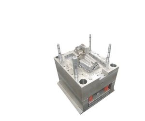
drawing the mold structure and part drawings is an essential step in the mold design process. It is crucial to have a clear understanding of the part geometry and the desired mold structure before proceeding with mold design and manufacturing. Here's how the process typically unfolds:
- Part Drawings: The first step is to create detailed part drawings or 3D models of the plastic component you want to mold. These drawings or models define the part's dimensions, features, tolerances, and any critical design considerations.
- Mold Conceptualization: Once the part drawings are available, the mold designer can start conceptualizing the mold structure. This involves determining the number of cavities, gate locations, runner systems, ejection methods, cooling channels, and other essential mold components based on the part design.
- Mold Base Selection: The mold base is the foundation of the mold structure. The mold designer selects an appropriate mold base size and configuration that can accommodate the required number of cavities and accommodate the part's size.
- Mold Layout: The mold layout is a preliminary representation of the mold structure, showing the positioning of various components within the mold base. This includes the part cavity layout, runner system, gate locations, ejection system, and cooling channels.
- Detailed Mold Design: With the mold layout as a guide, the designer proceeds to create a detailed mold design using computer-aided design (CAD) software. The mold design includes individual part drawings for each mold component, such as the cavity, core, slider, ejector pins, and cooling system.
- Mold Assembly Drawing: The mold designer then creates an assembly drawing, which brings together all the individual part drawings to show how the mold components fit together. The assembly drawing provides a comprehensive overview of the mold structure.
- Mold Analysis: Before finalizing the mold design, it is common to conduct mold flow analysis and simulation to optimize the design and identify potential issues, such as filling imbalances, warpage, or air traps.
- Manufacturing Considerations: During the mold design process, the designer must consider manufacturing constraints, such as tooling capabilities, available materials, and cost-effectiveness.
- Iterative Process: Mold design is often an iterative process, with feedback and revisions made as needed to ensure the mold can produce high-quality parts.
By starting with part drawings and proceeding through the mold design process systematically, designers can ensure that the final mold is well-suited to produce the desired plastic components with accuracy and efficiency.
In the process of drawing the mold, we need to follow the drawing standards set by the country. However, in addition to these standards, we also need to combine the factory's standards and the factory's customized drawing methods. Before drawing the general assembly drawing of the mold, we need to draw the process drawing first, and the process drawing needs to meet the requirements of production drawings and process data.
In the process drawing, the dimensions guaranteed for the next process need to be marked on the drawing as "process dimensions". If no other processing operations are performed after molding except burr repair, the process drawing is the same as the production drawing. In order to better identify the part number, name, material, material shrinkage, drawing scale, etc., we can mark it below the process drawing.
Typically, the process flow is shown on the assembly drawing of the mold. In this way, we can ensure that the mold manufacturing process meets national standard requirements, and at the same time, we can flexibly adjust and optimize it based on the actual situation of the factory.
Mold design is a crucial aspect of the plastic injection molding process. It involves designing the structure of the mold and creating detailed part drawings that will be used to produce the final product. One of the essential steps in mold design is drawing the mold structure and part drawings. In this article, we will discuss why it is important to draw the mold structure and part drawings first in mold design.
Drawing the mold structure and part drawings first provides a clear understanding of the mold's dimensions and requirements. It allows the designer to visualize the mold structure and identify any potential design issues or areas that require modification. The mold structure drawing typically includes a front view, top view, and side view, providing a complete view of the mold's structure.
Part drawings are essential because they provide a detailed view of each part of the mold, including dimensions, tolerances, and surface finishes. Part drawings are critical for ensuring that each component of the mold fits together correctly and that the final product meets the required specifications. Part drawings are typically created in orthographic projection, which is a standard method used to create detailed engineering drawings.
Drawing the mold structure and part drawings first also helps in identifying the required manufacturing processes for each component. The manufacturing process can be identified by analyzing the complexity of the part's geometry, the required material properties, and the production volume. This information can be used to determine the best manufacturing process for each component and optimize the overall manufacturing process.
In conclusion, drawing the mold structure and part drawings first in mold design is essential for creating a successful mold design. It provides a clear understanding of the mold's dimensions and requirements, identifies potential design issues, and helps in identifying the required manufacturing processes for each component. By following this approach, designers can create accurate and efficient mold designs that meet the required specifications and produce high-quality products.
