Introduction
In modern manufacturing, efficiency is not just about speed—it is about precision, reliability, and the ability to handle complex work with minimal waste. Horizontal CNC design has emerged as a transformative approach that addresses all these demands. Unlike traditional machining setups, horizontal CNC machines position the spindle axis horizontally, enabling unique capabilities that vertical machines simply cannot match.
Whether you are machining large aerospace components, high-volume automotive parts, or intricate medical implants, the horizontal orientation offers distinct advantages. This guide explores the fundamentals of horizontal CNC design, its key components, how it works, and real-world applications that demonstrate its impact on manufacturing efficiency. By the end, you will understand why this technology has become essential for shops aiming to stay competitive.
What Is Horizontal CNC Design?
How Does It Differ from Vertical Machines?
Horizontal CNC design refers to computer-controlled machining where the spindle axis is oriented horizontally. This seemingly simple difference creates a cascade of operational advantages.
In a vertical CNC machine, the spindle points downward. The workpiece sits on a table that moves in X and Y axes, while the spindle moves in Z. This setup works well for many applications but has limitations. Chips tend to fall onto the work surface, requiring careful coolant management. Access to the workpiece can be restricted, especially for deep cavities or tall parts.
In a horizontal machining center (HMC) , the spindle sits parallel to the ground. The workpiece mounts on a pallet that rotates, allowing the cutting tool to approach from multiple angles without repositioning the part. Gravity pulls chips away from the cutting zone, improving chip evacuation and reducing recutting. This orientation also enables long-reach machining, making it ideal for deep cavities and large components.
What Makes Horizontal CNC Unique?
Several features set horizontal CNC machines apart. The horizontal worktable is typically larger and more robust than vertical machine tables, designed to support heavy workpieces weighing several tons. Many HMCs use a pallet system, allowing one pallet to be loaded while another is in the cutting cycle. This reduces idle time significantly.
The spindle orientation enables better coolant delivery. Coolant can be directed straight into the cutting zone, and gravity helps carry chips away. This results in cleaner cuts, better surface finishes, and longer tool life.
What Are the Key Components?
Understanding the components helps explain why horizontal CNC machines perform the way they do.
Horizontal Worktable
The horizontal worktable is the foundation of the machine. Made from high-strength materials like cast iron or steel alloys, it provides excellent vibration damping. In a large-scale horizontal machining center used for aerospace components, the worktable can support workpieces weighing several tons.
The worktable surface is precision-ground to ensure accurate workpiece placement. Many tables feature a T-slot or grid-hole system, allowing easy installation of fixtures. Some advanced HMCs use pallet changers that swap workpieces in seconds, keeping the spindle cutting continuously.
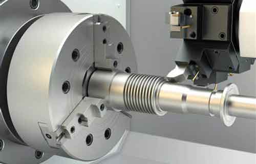
Spindle
The spindle is responsible for rotating the cutting tool. Different spindle types serve different applications. Belt-driven spindles offer good torque at lower speeds. Direct-drive spindles provide high-speed rotation with minimal vibration, reaching up to 20,000 RPM in high-end machines. Gear-driven spindles deliver high torque for machining hard materials like titanium alloys.
Spindle torque matters as much as speed. For heavy cuts in stainless steel or Inconel, high-torque spindles provide the necessary cutting force without stalling.
Control System
The control system is the brain of the machine. It interprets G-codes and M-codes, translating them into precise movements. Industry-standard systems like Fanuc, Siemens, and Heidenhain offer features like real-time monitoring, error correction, and adaptive control.
Modern control systems can adjust feed rates based on cutting loads. If the tool encounters a hard spot in the material, the system slows down to prevent breakage, then speeds up again when conditions allow. This adaptive machining improves tool life and protects the workpiece.
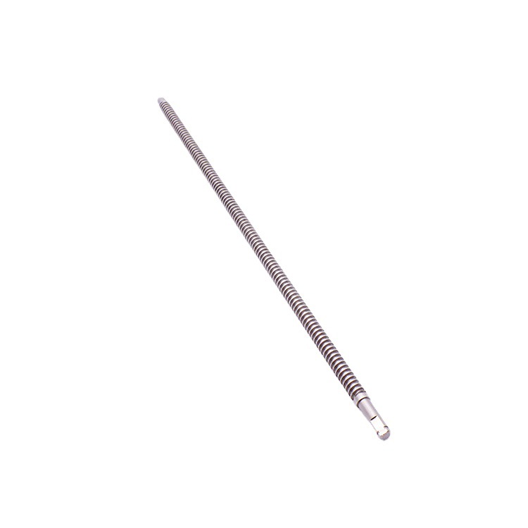
Feed System
The feed system moves the workpiece or tool in linear or rotary motion. Ball-screw mechanisms provide high-precision linear motion with minimal backlash. Servo motors control the rotation of the ball-screws with accuracy up to 0.001 mm.
In a horizontal CNC lathe, the feed system controls movement along X and Z axes. In a machining center, it controls X, Y, and Z axes plus rotary axes. The combination of precision ballscrews and servo motors ensures that every movement matches the programmed path.
How Does the Process Work?
Step 1: Design and Programming
The process begins with CAD modeling. An engineer creates a 3D model of the component using software like SolidWorks, CATIA, or AutoCAD. The model contains all geometric information—dimensions, shapes, tolerances.
Next comes CAM programming. The CAD model imports into CAM software, which generates the machining code. G-codes define axis movements. M-codes control auxiliary functions like spindle start and coolant flow. The programmer sets parameters such as spindle speed, feed rate, and depth of cut based on material and machining requirements.
Step 2: Toolpath Planning
The CAM software analyzes the CAD model to determine the optimal sequence of machining operations. For a part with holes, slots, and surfaces, it plans roughing passes to remove bulk material quickly, then finishing passes for high-precision surfaces.
Toolpath optimization minimizes machining time and tool wear. This involves avoiding unnecessary movements, reducing tool changes, and ensuring smooth transitions between operations. In a Yigu Technology project machining large aluminum housings, optimized toolpaths reduced cycle time by 22% without compromising quality.
Step 3: Material Setup and Machine Preparation
The appropriate workpiece material is selected based on final product requirements. For aerospace components, this might be aluminum alloy or titanium. The material is cut to size and mounted on the worktable using fixtures.
Cutting tools are selected and installed in the spindle or tool magazine. Each tool is designed for specific operations—end mills for milling, drills for hole-making, reamers for finishing.
Machine calibration ensures accurate positioning. This includes checking axis alignment and verifying measuring systems. On a horizontal CNC machine, spindle alignment with the worktable is critical for achieving tight tolerances.
Step 4: Machining Process
Once everything is set up, the machine executes the G-codes. The control system sends signals to servo motors, which drive the feed system and spindle. The spindle rotates the tool at specified speed while the feed system moves the workpiece or tool along the programmed path.
During machining, operators monitor the process using sensors and the machine control panel. If issues arise—excessive tool wear or dimensional deviation—adjustments can be made in real time. Some machines feature adaptive control that automatically adjusts feed rates to maintain optimal cutting conditions.
Step 5: Quality Inspection
In-process inspection uses touch-probe systems to measure workpiece dimensions during machining. This allows immediate correction if tolerances drift.
After machining, final inspection uses coordinate measuring machines (CMMs) to verify all dimensions against the original design. If parts do not meet requirements, they may be re-machined or scrapped. With proper process control, scrap rates below 2% are achievable.
Where Is Horizontal CNC Used?
Aerospace Industry
In aerospace, component precision is non-negotiable. Horizontal CNC design is extensively used for manufacturing aircraft engine components, structural frames, and landing gear parts.
Turbine blades, for example, are made from nickel-based superalloys that are difficult to machine. Horizontal CNC machines handle these materials with high-speed spindles and rigid construction. The horizontal orientation allows long-reach machining for deep blade cavities.
Case Study: Aerospace Compressor Blades
An aerospace company struggled with manufacturing a new compressor blade design. The blade had a complex airfoil shape with tolerances of ±0.05 mm. Their conventional machining process was time-consuming and resulted in a 20% rejection rate due to dimensional inaccuracies.
After switching to a horizontal machining center with a 15,000 RPM spindle and precision feed system, results improved dramatically. Production time dropped by 30%. Rejection rates fell below 5%. The improved accuracy also enhanced aerodynamic performance, contributing to a 5% reduction in engine fuel consumption.
Automotive Manufacturing
The automotive industry relies on horizontal CNC for engine blocks, transmission components, and drivetrain parts. Engine blocks—whether cast iron or aluminum—require precise machining of cylinder bores, coolant passages, and bolt holes. Horizontal machines handle these large castings efficiently.
Case Study: Transmission Gears
An automotive supplier needed to increase production capacity for transmission gears while maintaining quality. Their traditional process produced only 50 gears per day, with an 8% defect rate related to tooth profile accuracy.
They installed a horizontal CNC gear-hobbing machine with an advanced control system that enabled quick changeovers between gear types. Production increased to 150 gears per day—a threefold increase. Defect rates dropped to 2%. The improved quality led to a 40% increase in orders within one year.
Medical Device Manufacturing
Medical implants demand precision, biocompatibility, and customization. Horizontal CNC design enables production of orthopedic implants, dental components, and surgical instruments with tight tolerances.
Custom hip and knee replacements are machined from titanium alloys to match each patient's unique anatomy. The high precision ensures perfect fit, reducing complications and improving outcomes. Small dental implants require equally tight tolerances for successful osseointegration.
What Are the Efficiency Benefits?
Reduced Setup Time
Pallet systems are a game-changer for efficiency. While one pallet is being machined, the operator loads the next workpiece on a second pallet. When the machining cycle completes, the pallet swaps in seconds. This eliminates setup time from the machining cycle.
In high-mix, low-volume production, this capability is invaluable. A Yigu Technology client machining medical implants reduced setup-related downtime by 75% after adopting a horizontal CNC with pallet changer.
Better Chip Management
Gravity works in your favor with horizontal CNC. Chips fall away from the cutting zone rather than accumulating on the workpiece. This reduces recutting, improves surface finish, and extends tool life.
Effective chip evacuation also allows higher cutting parameters. Without chips interfering, speeds and feeds can be increased, further improving productivity.
Higher Spindle Utilization
Because pallet systems keep the spindle cutting while operators perform other tasks, spindle utilization rates climb. While vertical machines often achieve 40–50% spindle running time, horizontal machines with pallet changers routinely achieve 85–90% .
Improved Accuracy
The horizontal orientation provides better support for large workpieces. Gravity helps seat the workpiece firmly against fixtures. This stability translates to tighter tolerances and better surface finishes.
What Are the Limitations?
Higher Initial Cost
Horizontal CNC machines represent a significant investment. A new horizontal machining center with pallet changer typically costs 30–50% more than a comparable vertical machine. Installation, training, and tooling add to the upfront expense.
Floor Space Requirements
Horizontal machines have a larger footprint than vertical machines of comparable capacity. The pallet system adds width, and the overall configuration requires more floor space. Shops with limited space may need to consider this trade-off.
Maintenance Complexity
Horizontal CNC machines have more moving parts than vertical machines—pallet changers, additional axes, more complex coolant systems. Maintenance requires specialized technicians. However, the increased productivity often justifies the higher maintenance costs.
Conclusion
Horizontal CNC design has fundamentally changed what manufacturers can achieve. Its combination of precision, efficiency, and versatility makes it indispensable across aerospace, automotive, medical, and many other industries.
The key takeaways are clear. Horizontal orientation enables better chip management and long-reach machining. Pallet systems eliminate setup downtime and maximize spindle utilization. Advanced control systems provide real-time monitoring and adaptive control. Real-world case studies demonstrate measurable improvements—30% faster production, rejection rates cut by 75%, and threefold increases in output.
While initial costs and floor space requirements are considerations, the productivity gains typically justify the investment. For manufacturers facing tight tolerances, complex geometries, or high-volume demands, horizontal CNC design offers a proven path to improved efficiency and competitiveness.
FAQ
What is the main difference between horizontal and vertical CNC machines?
The spindle axis orientation is the primary difference. Horizontal CNC machines have a horizontal spindle, allowing long-reach machining and better chip evacuation. Vertical CNC machines have a vertical spindle, which is often better for smaller parts where gravity-assisted chip removal from the top is convenient. Horizontal machines typically have larger worktables and pallet systems that reduce setup time.
How do I choose the right horizontal CNC machine for my needs?
Start by considering workpiece size and weight—horizontal machines vary widely in capacity. Evaluate precision requirements; higher-end machines offer better accuracy but cost more. Look at spindle speed and torque based on your materials. Consider the pallet system—multiple pallets increase throughput. Finally, factor in brand reputation and after-sales support, as reliable service is critical for minimizing downtime.
Is horizontal CNC worth the higher initial cost?
For many applications, yes. The productivity gains from reduced setup time, higher spindle utilization, and better chip management often pay back the investment within 12–24 months. For high-volume production or complex parts requiring multiple operations, the return on investment is typically faster. For very small shops with limited capital or simple parts, a vertical machine may be sufficient.
Can horizontal CNC machines handle small parts?
Yes. While horizontal machines are known for large workpieces, they can also machine small parts efficiently. Pallet systems allow multiple small parts to be fixtured on a single pallet, increasing throughput. The precision and stability of horizontal machines benefit small parts requiring tight tolerances, such as medical implants or electronic components.
Contact Yigu Technology for Custom Manufacturing
Ready to improve your machining efficiency? Yigu Technology specializes in custom manufacturing using horizontal CNC equipment. Our engineering team optimizes toolpaths, selects appropriate tooling, and applies proven processes to deliver precision parts on time. Contact us today to discuss your project requirements.