The seemingly straightforward process of CAD model design, or computer-aided design, belies a complexity that extends far beyond the simple creation of digital representations. While superficially involving the generation of 3D models for applications ranging from additive manufacturing and rapid prototyping to sophisticated simulations and exhaustive documentation, the reality is a multifaceted interplay of algorithmic precision, intuitive design, and unpredictable emergent properties.
Consider the foundational act: the genesis of a digital object. It's not merely a matter of sketching in pixels; it's the imposition of constraints and freedoms within a defined computational space. The choice of CAD software—AutoCAD's parametric precision, SolidWorks' intuitive assembly modeling, CATIA's dominance in aerospace—is not arbitrary; it dictates the very grammar of the design process, influencing not only the efficiency but the inherent limitations and possibilities of the final product. This initial decision sets the stage for a cascade of choices, each with potentially unforeseen consequences.
The importance of CAD transcends mere efficiency gains. While the accelerated design cycles and reduced material waste are undeniable advantages, the true power lies in the iterative refinement facilitated by the digital medium. The ability to instantly modify, analyze, and simulate design iterations under diverse conditions—stress testing a bridge under seismic load, predicting airflow around a vehicle—allows for the exploration of a design space far exceeding the capabilities of traditional methods. This iterative process, however, is not always predictable. Unexpected interactions between design parameters, subtle flaws only revealed through rigorous simulation, and the inherent limitations of the chosen software can lead to unforeseen challenges and necessitate creative solutions.
The creation of a CAD model is not a linear progression, but a recursive journey through a landscape of possibilities. Beginning with rudimentary geometric primitives—extruded solids, revolved surfaces, NURBS curves—the designer crafts a digital artifact through a process of successive refinement. The addition of textures, the manipulation of lighting, the application of complex material properties—these are not mere aesthetic embellishments, but critical components that profoundly impact the final simulation results and the overall performance of the physical object. The final rendering, far from a simple visualization, serves as a crucial validation step, revealing potential inconsistencies or areas requiring further refinement. The export of the model, too, is a critical juncture, demanding careful consideration of file formats and data integrity to ensure compatibility across different software platforms and manufacturing processes. The seemingly simple act of "saving" the file becomes a critical moment in the translation of the digital design into the physical world. The unpredictable nature of this transition underscores the inherent complexities and challenges inherent in CAD model design.
What is CAD Modelling?
CAD modelling is the use of computers to create, modify, analyze and optimize the design of an object or structure. CAD software allows users to create 2D drawings or 3D models that represent the geometry, dimensions, properties and appearance of the object or structure. CAD models can be viewed from different angles, zoomed in and out, and manipulated in various ways.
CAD modelling has many advantages over manual drafting, such as:
- Higher accuracy and precision
- Faster design process and revisions
- Easier collaboration and communication
- Better visualization and simulation
- Lower cost and waste
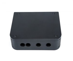
CAD modelling is used in many industries and fields, such as:
- Architecture and engineering
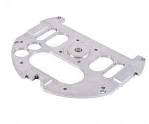
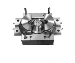
- Manufacturing and fabrication
- Product design and development
- Animation and gaming
- Education and research
Why is CAD Modelling Important?
The transformative influence of Computer-Aided Design (CAD) modeling on contemporary engineering and manufacturing is undeniable, extending far beyond mere visualization. Its impact reverberates through every stage of the product lifecycle, fundamentally reshaping design methodologies and accelerating innovation. The creation of intricate digital surrogates, achieved through sophisticated software, allows for a level of pre-production analysis previously unattainable. This transcends simple representation; it empowers predictive modeling, enabling engineers to probe the very essence of a design's performance envelope before a single physical prototype is conceived.
The acceleration of product development cycles is not merely an ancillary benefit; it's a paradigm shift. The iterative design process, once a laborious sequence of physical prototyping and testing, is now a fluid, computationally driven dance of refinement. Multiple design iterations, previously constrained by time and cost, are now readily explored, significantly reducing time-to-market and enhancing responsiveness to evolving market demands. This agility is not simply efficient; it's a competitive advantage in today's rapidly evolving landscape.
Furthermore, CAD modeling transcends the limitations of physical experimentation. Through sophisticated simulations – encompassing stress analysis, computational fluid dynamics (CFD), and thermal modeling – engineers can subject virtual prototypes to rigorous testing, identifying latent flaws and optimizing performance characteristics with unprecedented precision. This virtual testing ground allows for the proactive identification and mitigation of potential failure points, leading to inherently more robust and reliable products.
The collaborative potential of CAD is equally transformative. Multidisciplinary teams, geographically dispersed yet seamlessly interconnected, can concurrently manipulate and analyze the same digital model, fostering a dynamic exchange of ideas and expertise. This real-time collaboration transcends the limitations of traditional communication channels, streamlining decision-making processes and ensuring design coherence across all stakeholders.
The integration of CAD with other computer-aided engineering (CAE) and manufacturing (CAM) tools further amplifies its impact. The seamless transition from CAD models to finite element analysis (FEA), CFD simulations, and CNC toolpath generation represents a unified, digitally driven workflow. This eliminates data inconsistencies and ensures a harmonious progression from conceptual design to final production, minimizing errors and maximizing efficiency.
Beyond technical applications, CAD modeling significantly enhances communication. The ability to present clients, suppliers, and manufacturers with photorealistic 3D representations fosters a shared understanding of design intent, mitigating misinterpretations and ensuring accurate manufacturing execution. This clarity extends to detailed design documentation, providing comprehensive specifications that leave no room for ambiguity.
In conclusion, CAD modeling is not merely a tool; it's a fundamental pillar of modern product development. Its influence extends far beyond design visualization, impacting every facet of the process, from conceptualization and simulation to manufacturing and delivery. The ongoing evolution of CAD technology promises even greater capabilities, solidifying its indispensable role in driving innovation and shaping the future of engineering and manufacturing.
How to Design a CAD Model Step by Step
The process of designing a CAD model may vary depending on the type, complexity and purpose of the model, as well as the software used. However, there are some common steps that can be followed to create a basic CAD model:
Choose a CAD Software
The first step is to choose a suitable CAD software that meets your needs and preferences. There are many types of CAD software available, such as:
- 2D CAD software: These are programs that allow you to create 2D drawings or sketches of your design. Examples are AutoCAD, DraftSight and LibreCAD.
- 3D CAD software: These are programs that allow you to create 3D models or solids of your design. Examples are SolidWorks, Fusion 360 and SketchUp.
- Parametric CAD software: These are programs that allow you to define the parameters or constraints of your design, such as dimensions, angles, relations and formulas. The software then automatically updates the model according to the changes made to the parameters. Examples are Inventor, Solid Edge and Creo.
- Direct CAD software: These are programs that allow you to directly manipulate the geometry or features of your design without relying on parameters or constraints. The software then automatically adapts the model according to the changes made to the geometry or features. Examples are Onshape, Rhino and FreeCAD.
- Surface CAD software: These are programs that allow you to create smooth curves or surfaces for your design. The software then converts the curves or surfaces into solid models. Examples are CATIA, NX and Alias.
Some factors that you may consider when choosing a CAD software are:
- The type of model you want to create (2D or 3D)
- The level of detail and complexity you need for your model
- The compatibility with other software or formats you may use
- The availability of tutorials, support and community resources
- The cost and licensing options
Define the Design Requirements
The next step is to define the design requirements or specifications for your model. These are the criteria or constraints that your model must meet or follow, such as:
- The size and shape of the model
- The function and purpose of the model
- The materials and properties of the model
- The standards and regulations that apply to the model
- The budget and timeline for the model
The design requirements help you to:
- Focus on the essential aspects of your model
- Avoid unnecessary or conflicting features or elements
- Evaluate the feasibility and viability of your model
- Measure the quality and performance of your model
You can define the design requirements by:
- Conducting research and analysis of the problem or need that your model addresses
- Consulting with stakeholders, customers or clients who are involved or affected by your model
- Reviewing existing or similar models or solutions that may inspire or inform your model
- Brainstorming and sketching possible design ideas or concepts for your model
Sketch the Basic Shape
The next step is to sketch the basic shape or outline of your model using the CAD software. This is the initial stage of creating your model, where you define the main geometry or structure of your model. You can sketch the basic shape by:
- Choosing a suitable plane or view to start your sketch (such as front, top or right)
- Using drawing tools such as lines, arcs, circles, rectangles, polygons and splines to create the profile or contour of your model
- Using editing tools such as trim, extend, offset, fillet and chamfer to modify or refine your sketch
- Using dimensioning tools such as linear, angular, radial and diametral to specify the size and position of your sketch
- Using constraint tools such as horizontal, vertical, parallel, perpendicular and tangent to control the shape and orientation of your sketch
Depending on the type of CAD software you use, you may be able to:
- Extrude, revolve, sweep or loft your sketch to create a 3D solid or surface from it
- Mirror, pattern, copy or move your sketch to create multiple instances or variations of it
- Combine, subtract, intersect or split your sketch to create complex shapes from simple ones
Add Details and Features
The next step is to add details and features to your model using the CAD software. This is the stage where you enhance and customize your model by adding elements or components that improve its appearance, functionality or performance. You can add details and features by:
- Using feature tools such as hole, fillet, chamfer, shell and rib to create common shapes or operations on your model
- Using sketch tools such as text, symbol, image and hatch to create annotations or decorations on your model
- Using assembly tools such as mate, align, constrain and explode to create relationships or connections between different parts of your model
- Using pattern tools such as linear, circular, curve-driven and fill to create repeated features or elements on your model
Depending on the type of CAD software you use, you may be able to:
- Import external files or data such as images, drawings, scans or point clouds to create or modify your model
- Apply materials and colors such as metal, plastic, wood or glass to define the physical properties and appearance of your model
- Apply textures and decals such as bump maps, normal maps or stickers to create realistic effects or details on your model
Apply Materials and Colors
The next step is to apply materials and colors to your model using the CAD software. This is the stage where you define the physical properties and appearance of your model by assigning materials and colors to different parts or faces of your model. You can apply materials and colors by:
- Choosing a suitable material library or database that contains predefined materials and colors for various applications and industries
- Selecting a material category such as metal, plastic, wood or glass that matches the type of material you want for your model
- Selecting a material subcategory such as steel, aluminum, copper or brass that matches the specific material you want for your model
- Selecting a material variant such as polished, brushed, matte or glossy that matches the desired finish or effect for your material
- Selecting a color option such as RGB, CMYK, HSL or HEX that matches the color system you want for your material
Depending on the type of CAD software you use, you may be able to:
- Create custom materials and colors by adjusting parameters such as density, elasticity, reflectivity or transparency
- Apply textures and decals such as bump maps, normal maps or stickers to create realistic effects or details on your material
- Apply lighting and shadows such as ambient light, point light, spot light or directional light to create realistic illumination on your material
Export and Save the CAD Model
The final step is to export and save the CAD model using the CAD software. This is the stage where you prepare and store your model for future use or sharing.
After you have finished designing your CAD model, you may want to export and save it in a different file format. This can help you share your model with others, use it in other software applications, or print it with a 3D printer. To export and save your CAD model, follow these steps:
- Click on the File menu and select Export.
- Choose the file format you want to export your model to. Some common formats are STL, OBJ, STEP, and IGES.
- Specify a name and location for your exported file.
- Click on Save to complete the export process.
You have successfully exported and saved your CAD model. You can now open it in another program or device, or send it to someone else.