What is Injection Mold Runner Design
Definition
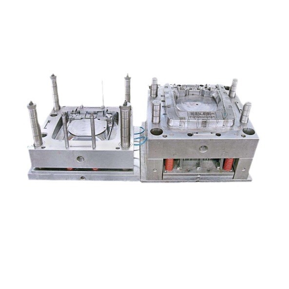
Injection mold runner design is a fundamental and crucial aspect of the injection molding process. It refers to the strategic planning and creation of the channels within an injection mold through which the molten plastic material, known as the polymer melt, flows from the injection machine's nozzle to the cavities where the final plastic products are formed. These channels, collectively called the runner system, play a pivotal role in ensuring the smooth and efficient filling of the cavities, which is essential for the production of high - quality plastic parts.
Think of the runner system as the circulatory system of the injection mold. Just as the circulatory system in our bodies is responsible for transporting vital substances like blood to all parts of the body, the runner system in injection molding is responsible for delivering the molten plastic to every corner of the mold cavities. If the runner system is not designed properly, it can lead to a host of problems, similar to how a malfunctioning circulatory system can cause health issues.
The runner system consists of several components, with the main ones being the main runner and the sub - runners (also known as branch runners or secondary runners). The main runner is the primary channel that directly connects to the injection machine's nozzle. It serves as the main artery, carrying the large volume of molten plastic from the source. The sub - runners, on the other hand, branch out from the main runner, much like smaller blood vessels branching out from the aorta. They distribute the molten plastic to the individual cavities in a multi - cavity mold or to different sections of a complex single - cavity mold.
Key Elements of Injection Mold Runner Design
Runner Types
Circular Runners
Circular runners are highly regarded in injection mold runner design for several reasons. One of their most significant advantages is their low pressure - drop. When the molten plastic flows through a circular runner, the cross - sectional area allows for a more laminar flow, reducing the resistance and pressure loss during the injection process. This makes them particularly suitable for large - scale molds. For example, in the production of large plastic containers or automotive parts with large - scale molds, circular runners can ensure that the molten plastic reaches all parts of the mold cavity evenly, without significant pressure differences.
Compared to other runner types, circular runners have a uniform wall thickness around the perimeter. This uniform thickness helps in maintaining a consistent temperature distribution within the runner, as heat transfer is more even. In contrast, some other runner types may have uneven wall thicknesses, which can lead to variations in the cooling rate of the molten plastic and potentially cause defects in the final product.
Trapezoidal Runners
Trapezoidal runners are another common type used in injection molding. They are widely favored because they are easy to machine. Manufacturers can create trapezoidal runners with relative ease using standard machining processes, which reduces production time and costs. This makes them a popular choice for common molds, especially those used in mass - production of everyday plastic items like plastic toys, household utensils, etc.
For instance, in a factory that produces plastic spoons in large quantities, trapezoidal runners are often employed. The simplicity of machining these runners allows the mold - making process to be more efficient. Also, the trapezoidal shape can provide a good balance between flow characteristics and material usage. The sloped sides of the trapezoid can help in the smooth flow of the molten plastic, while not using excessive amounts of material for the runner system.
Gate Types
Side Gates
Side gates are commonly used for parts with simple shapes. They are relatively easy to design and implement in the mold. For products like flat plastic plates or simple - shaped plastic covers, side gates work well. The reason is that these products do not have complex internal geometries or high - precision requirements that would demand more sophisticated gate types.
When a side gate is used, the molten plastic enters the cavity from the side. This can be beneficial as it allows for a straightforward filling process. For example, in the production of a simple plastic clipboard, a side gate can be placed on the long edge of the mold cavity. The molten plastic flows in from the side, filling the cavity evenly and creating a well - formed clipboard. However, side gates may leave a visible gate mark on the side of the part, so they are not ideal for products where aesthetics are a crucial factor.
Submarine Gates
Submarine gates, also known as tunnel gates, have a unique feature. They can automatically cut off the runner from the part during ejection. This is a great advantage as it eliminates the need for manual trimming of the runner from the finished product.
A common application scenario is in the production of small plastic components such as electronic connectors. These connectors are often small and require a clean separation from the runner system. With a submarine gate, during the ejection process, the gate breaks away from the part, leaving a relatively clean edge. The runner can then be easily removed from the mold, and the part is ready for further processing or assembly without the need for additional labor - intensive trimming operations.
Pin - point Gates
Pin - point gates are suitable for high - precision and small - sized parts. The small diameter of the pin - point gate allows for better control over the flow of the molten plastic. When producing small plastic gears for watches or tiny electronic components, pin - point gates are often the gate type of choice.
The small gate diameter creates a high - shear rate when the molten plastic passes through it. This high - shear rate can help to reduce the viscosity of the plastic, enabling it to flow more easily into the small and detailed cavities. For example, in the production of a micro - sized plastic gear with fine teeth, a pin - point gate ensures that the plastic fills all the small tooth - shaped cavities accurately, resulting in a high - precision gear. Also, the small gate mark left by the pin - point gate is less noticeable on small parts, which is important for maintaining the overall aesthetics and functionality of the product.
Cold Slug Wells
Cold slug wells play a vital role in the injection molding process. Their primary function is to trap the cold plastic that is at the front of the molten plastic flow at the beginning of the injection process. This cold plastic, if allowed to enter the mold cavity, can cause defects such as short shots or poor surface quality in the final product.
Cold slug wells with ejector pins offer an additional advantage. After the injection cycle, the cold slug (the trapped cold plastic) can be easily removed from the mold. The ejector pin pushes out the cold slug, ensuring that it does not remain in the cold slug well and interfere with subsequent injection cycles. This is especially important in high - volume production, where a clean and efficient removal of cold slugs is necessary to maintain a high production rate and product quality.
Common Mistakes in Injection Mold Runner Design
Improper Runner Sizing
Improper runner sizing is a prevalent mistake in injection mold runner design that can have a significant impact on the quality of the final product. If the runner diameter is too large, it can lead to excessive material consumption. For example, in a multi - cavity mold for producing small plastic parts, a large - diameter runner would waste a substantial amount of plastic material, increasing production costs. Moreover, a large runner takes longer to cool down. This extended cooling time can slow down the overall injection - molding cycle, reducing productivity.
On the other hand, if the runner diameter is too small, it creates high resistance to the flow of the molten plastic. This high resistance results in a significant pressure - drop during the injection process. When the pressure drop is too large, the molten plastic may not be able to reach all parts of the mold cavity evenly. This can lead to incomplete filling of the cavities, causing short - shot defects. For instance, in the production of a complex - shaped plastic toy with multiple thin - walled sections, a small - diameter runner might prevent the plastic from flowing into some of the narrow cavities, resulting in a defective toy.
Incorrect Gate Placement
Incorrect gate placement is another critical error that can cause a variety of problems in injection - molded parts. When the gate is placed in an inappropriate location, it can lead to uneven filling of the mold cavity. For example, if the gate is placed too close to one side of a rectangular - shaped plastic panel, the plastic will flow more quickly towards that side, while the other side may experience slower filling. This uneven filling can cause warping of the panel as the two sides cool and solidify at different rates.
Another issue associated with incorrect gate placement is the formation of weld lines or knit lines. These lines occur when two or more streams of molten plastic meet during the filling process. If the gate is placed in a way that causes the plastic to flow around obstacles or into different sections of the cavity separately, these streams may not fuse together properly when they meet. Weld lines can weaken the mechanical strength of the part. In the case of a plastic automotive component, such as a bumper, weld lines can reduce the impact - resistance of the bumper, making it more likely to crack or break in a collision.
Neglecting Cold Slug Wells
Cold slug wells are an essential part of the injection mold runner design, and neglecting them can lead to serious product defects. At the beginning of the injection process, the plastic at the front of the molten plastic flow is often cooler than the rest of the material. This cold plastic, also known as a cold slug, has a higher viscosity. If there are no cold slug wells in the runner system, this cold slug can enter the mold cavity.
Once the cold slug enters the cavity, it can cause a short - shot defect. Since the cold slug has a higher viscosity, it does not flow as easily as the hotter plastic. As a result, it can block the flow path and prevent the rest of the molten plastic from filling the cavity completely. In addition, the cold slug can cause surface defects on the final product. For example, it can create a rough or uneven surface texture, which is unacceptable for products where aesthetics are important, such as consumer electronics housings or decorative plastic items. Cold slugs can also disrupt the internal structure of the part, affecting its mechanical properties.
Yigu Technology's Perspective
As a non - standard plastic metal products custom supplier, Yigu Technology attaches great importance to injection mold runner design. In our experience, the key point in runner design is to ensure a perfect balance between material flow and product quality.
When designing runners, we focus on precise sizing calculations. We use advanced simulation software to analyze the flow behavior of molten plastic, which helps us determine the optimal runner diameter and length. This not only reduces material waste but also improves production efficiency.
For gate types, we carefully select based on the product's shape, size, and quality requirements. Our engineers are proficient in using different gate types, such as side gates for simple - shaped products to simplify the design and submarine gates for products requiring automatic separation to improve the production process. Additionally, we never neglect the importance of cold slug wells. Equipping molds with well - designed cold slug wells is a standard operation in our production, ensuring that the final products are free from defects caused by cold slugs.
