1. Core Differences in Process Mechanics
1.1 How Milling Works
Milling is a machining process that uses a rotating multi-toothed cutter to remove material from the surface of a workpiece. This process is highly versatile and can create a wide variety of shapes and features. The cutter in milling operations can move along multiple axes, with 3 - 5 axes being commonly used in modern CNC (Computer Numerical Control) milling machines. This multi - axis movement is what enables the creation of intricate shapes.
For instance, consider the manufacturing of a slot in a metal block. The milling cutter, with its sharp teeth, rotates at high speeds while being fed into the workpiece. As it moves along the pre - programmed path, it gradually removes material, creating a slot with precise dimensions. When it comes to more complex shapes like gears, the milling process becomes even more fascinating. Gears have complex tooth profiles, and a milling machine can accurately machine these profiles by carefully controlling the movement of the cutter in multiple axes.
In a typical milling operation, the cutting speed, feed rate, and depth of cut are crucial parameters. The cutting speed is the speed at which the teeth of the milling cutter move relative to the workpiece. A higher cutting speed can increase the material removal rate but also generates more heat, which can affect the tool life and the quality of the workpiece surface. The feed rate is the rate at which the workpiece is moved relative to the cutter. A proper feed rate ensures that the cutter removes material smoothly without over - stressing the tool or causing excessive vibrations. The depth of cut determines how much material is removed in a single pass.
1.2 The Mechanics of Turning
Turning, on the other hand, is a machining process where the workpiece rotates while a stationary cutting tool shapes its outer or inner diameters. This process is especially well - suited for creating cylindrical parts.
Take the production of a simple shaft as an example. The shaft blank is clamped onto a chuck or between centers on a lathe. As the shaft rotates at a high speed, a cutting tool, which is fixed in a tool post, is brought into contact with the rotating workpiece. The cutting tool can move in two main directions: longitudinally (parallel to the axis of rotation of the workpiece) and radially (perpendicular to the axis of rotation). By carefully controlling the movement of the cutting tool in these directions, the outer diameter of the shaft can be precisely machined to the desired dimensions.
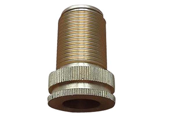
When it comes to creating threaded components, turning is the go - to process. The lathe can be programmed to move the cutting tool in a helical path, which results in the formation of threads on the surface of the workpiece. For Yigu Technology example, a common bolt is produced by turning operations where the outer diameter is first machined to the correct size, and then the threads are cut using a threading tool.
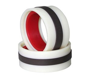
Bushings, which are cylindrical components with a hole in the center, are also typically made using turning. The outer diameter of the bushing is machined first, and then an internal boring operation is performed to create the central hole. In modern CNC lathes with live tooling, additional milling - like features can be added during the turning process. For example, cross holes can be drilled or milled in a shaft while it is being turned, without the need to transfer the workpiece to a different machine.
Similar to milling, in turning, parameters such as spindle speed (equivalent to the cutting speed in milling as it determines the speed of the workpiece rotation), feed rate (how fast the cutting tool moves relative to the rotating workpiece), and depth of cut are crucial. The spindle speed affects the cutting forces and the surface finish of the workpiece. A higher spindle speed can result in a smoother surface finish but may also increase the risk of tool wear if not properly controlled. The feed rate determines the amount of material removed per revolution of the workpiece, and the depth of cut controls how much material is removed in a single pass of the cutting tool.
The following Yigu Technology table summarizes the basic differences in process mechanics between milling and turning:
| Aspect | Milling | Turning |
| Moving Component | Rotating multi - toothed cutter; workpiece may also move in some setups | Rotating workpiece; stationary cutting tool |
| Axes of Movement | 3 - 5 axes common for cutter movement | Mainly 2 axes (longitudinal and radial) for tool movement relative to rotating workpiece |
| Typical Shapes Produced | Slots, gears, contoured surfaces, complex 3D shapes | Cylindrical parts, shafts, bushings, threaded components |
2. Comparative Analysis: Key Performance Metrics
When it comes to choosing between milling and turning for a machining project, understanding the key performance metrics of each process is crucial. These metrics can help manufacturers make informed decisions based on factors such as shape complexity, accuracy requirements, surface finish, material removal rate, and production time.
2.1 Shape Complexity and Axes of Movement
Milling is the clear choice when it comes to creating complex 3D shapes, flat surfaces, and slots. The ability of the milling cutter to move along 3 - 5 axes allows for the creation of highly intricate geometries. For example, in the aerospace industry, milling is used to create the complex shapes of engine components such as compressor blades. These blades have a combination of curved surfaces, thin walls, and precise features, which can only be achieved through the multi - axis movement of a milling cutter.
On the other hand, turning is best suited for producing cylindrical, conical, or threaded forms. The rotational symmetry of the workpiece in turning limits the types of shapes that can be created. However, for parts like shafts, bushings, and threaded fasteners, turning offers high - precision manufacturing capabilities. A simple shaft with a constant diameter can be quickly and accurately machined on a lathe.
The following Yigu Technology table summarizes the relationship between shape complexity and axes of movement in milling and turning:
| Process | Typical Shapes Produced | Axes of Movement |
| Milling | 3D shapes, flat surfaces, slots | 3 - 5 axes for complex paths |
| Turning | Cylindrical, conical, or threaded forms | 2 - 3 axes for rotational symmetry |
2.2 Accuracy and Tolerance
Accuracy is a critical factor in machining, and both milling and turning can achieve high levels of precision. However, the achievable tolerance levels can vary between the two processes.
In milling, typical tolerance levels range from ±0.02mm - ±0.05mm. This level of accuracy is sufficient for many applications, especially in industries such as automotive manufacturing, where parts need to fit together precisely but do not require the highest levels of precision. For example, when milling engine blocks, the tolerances on the bore diameters and surface flatness need to be within a certain range to ensure proper engine performance.
Turning, on the other hand, can achieve even higher accuracy, with tolerance levels typically ranging from ±0.01mm - ±0.03mm. This makes turning the preferred process for applications where extremely tight tolerances are required, such as in the medical device industry. Components like surgical implants often need to be manufactured with very tight tolerances to ensure proper fit and function within the human body.
2.3 Surface Finish
The surface finish of a machined part is another important consideration, as it can affect the part's functionality, appearance, and durability.
Milling can produce a surface finish with a roughness value (Ra) typically ranging from Ra0.8 - Ra3.2. The surface finish in milling depends on several factors, including the cutting speed, feed rate, cutter geometry, and the number of passes. For example, a higher cutting speed and a smaller feed rate can result in a smoother surface finish. However, these parameters also need to be balanced with the material removal rate and tool life.
Turning can achieve a better surface finish compared to milling, with Ra values typically ranging from Ra0.4 - Ra1.6. The continuous contact between the cutting tool and the rotating workpiece in turning results in a more consistent removal of material, which contributes to a smoother surface. In applications such as optical components manufacturing, where a very smooth surface finish is required, turning can be used to achieve the desired surface quality.
2.4 Material Removal Rate
The material removal rate (MRR) is an important metric for assessing the productivity of a machining process.
In milling, the material removal rate can vary depending on the cutter size, spindle speed, and feed rate. Generally, milling has a moderate to high material removal rate, especially when using large - diameter cutters and high - speed spindles. For example, in rough milling operations, large amounts of material can be removed quickly to bring the workpiece close to its final shape. However, in finish milling, the material removal rate is usually reduced to achieve the desired surface finish and accuracy.
Turning typically has a high material removal rate, especially for cylindrical parts. The direct contact between the cutting tool and the rotating workpiece allows for efficient removal of material. In addition, modern CNC lathes are capable of high - speed machining, which further increases the material removal rate. For example, when turning a large - diameter shaft, the lathe can remove material rapidly while maintaining high accuracy.
2.5 Production Time
Production time is a crucial factor in manufacturing, as it directly impacts the cost and efficiency of the production process.
For prototypes or small - batch production, milling can take 3 - 7 days, depending on the complexity of the part. The setup time for milling operations, especially for multi - axis machining, can be relatively long, as it involves programming the machine, setting up the fixtures, and selecting the appropriate cutting tools. However, once the setup is complete, milling can produce complex parts with high accuracy.
Turning, on the other hand, can produce simple parts in 2 - 5 days. The setup time for turning is generally shorter than that for milling, especially for parts with rotational symmetry. Once the workpiece is clamped onto the lathe, the machining process can start quickly. For example, producing a simple threaded bolt can be completed relatively quickly on a lathe.
The following Yigu Technology table provides a summary of the key performance metrics for milling and turning:
| Performance Metric | Milling | Turning |
| Shape Complexity | 3D shapes, flat surfaces, slots | Cylindrical, conical, or threaded forms |
| Axes of Movement | 3 - 5 axes for complex paths | 2 - 3 axes for rotational symmetry |
| Accuracy (Tolerance) | ±0.02mm - ±0.05mm | ±0.01mm - ±0.03mm |
| Surface Finish (Ra) | Ra0.8 - Ra3.2 | Ra0.4 - Ra1.6 |
| Material Removal Rate | Moderate to high (depends on cutter size) | High (direct tool contact) |
| Production Time | 3 - 7 days for prototypes | 2 - 5 days for simple parts |
3. Real-World Applications: When to Choose Which
3.1 Aerospace Component Example
In the aerospace industry, the choice between milling and turning is often dictated by the specific requirements of the components. For example, consider the manufacturing of jet engine parts. Turbine blades, which are critical components in jet engines, have complex aerodynamic profiles. These profiles are designed to optimize the flow of hot gases, thereby increasing the engine's efficiency. Milling is the preferred process for creating turbine blade prototypes. A 5 - axis milling machine can precisely carve out the intricate shapes of the turbine blades, including the curved surfaces and internal cooling channels. This level of precision is crucial as even the slightest deviation in the blade's shape can significantly affect the engine's performance.
On the other hand, the steel shafts in the jet engine are produced using turning. These shafts need to have high concentricity to ensure smooth rotation and reduce vibrations during engine operation. Turning is well - suited for this task as it can easily produce cylindrical parts with high precision. Additionally, turning is more cost - efficient for producing shafts compared to milling, as the process is relatively straightforward and requires fewer complex operations.
3.2 Automotive Innovation
In the automotive industry, the design and production of transmission components also showcase the distinct advantages of milling and turning. Transmission systems are complex, and their components need to be manufactured with high precision to ensure smooth gear shifting and efficient power transfer.
Milling is used to create the intricate gear teeth in transmissions. Gears are the heart of the transmission system, and the accuracy of their tooth profiles is essential for proper functioning. Milling allows for the creation of precise gear tooth shapes, whether they are straight, helical, or other specialized profiles. For example, in a manual transmission, the gear teeth need to mesh smoothly to enable seamless gear changes. Milling can achieve the tight tolerances required for these gear teeth, ensuring that the transmission operates quietly and efficiently.
Turning, on the other hand, is used to produce the smooth, concentric shafts in the transmission. These shafts are responsible for transmitting power from the engine to the wheels through the gears. The concentricity of the shafts is crucial for minimizing vibrations and ensuring efficient power transfer. A lathe can precisely machine the outer diameter of the shafts to the required dimensions, and if necessary, can also create internal features such as splines or holes.
By using a combination of milling and turning in transmission design, automotive manufacturers can achieve significant time savings. In fact, this hybrid approach can cut the development time by up to 40%. For instance, in the development of a new transmission for a high - performance vehicle, the use of milling for gear production and turning for shaft manufacturing allows for parallel processing of these components. This means that while the gears are being milled, the shafts can be simultaneously turned, reducing the overall production time and bringing the new transmission to market faster.
4. Conclusion: The Power of Process Selection
In the dynamic realm of manufacturing, milling and turning are not adversaries vying for supremacy but rather complementary cornerstones, each with its own set of unique capabilities. They are the yin and yang of the machining world, and understanding their distinct characteristics is the key to unlocking manufacturing excellence.
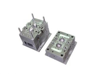
Milling, with its multi - axis prowess, is the go - to process for crafting complex geometries. It can transform a solid block of material into a work of art, whether it's a finely detailed mold for the plastics industry or a precision - engineered component for the electronics sector. The ability to create intricate 3D shapes, slots, and gears makes milling an indispensable tool in the manufacturing toolkit.
Turning, on the other hand, reigns supreme in the domain of cylindrical and threaded components. Its precision in creating concentric shafts and perfectly formed threads is unrivaled. In industries such as automotive and energy, where the reliability of components is crucial, turning plays a vital role.
At Yigu Technology, we firmly advocate for a data - driven approach to process selection. By analyzing the specific requirements of a design, such as shape complexity, accuracy, surface finish, and production volume, we can match the right machining process to the task at hand. This not only ensures the highest quality end - product but also optimizes production efficiency and cost - effectiveness.


