Introduction
In the dynamic realm of manufacturing, injection moulding stands as a cornerstone process, enabling the mass - production of a vast array of plastic products that permeate every aspect of our daily lives, from the tiniest components in electronics to large - scale automotive parts. At the heart of successful injection moulding lies injection mould design calculations, a discipline that combines engineering principles, material science, and mathematical precision.
The Significance of Injection Mould Design Calculations
Injection mould design calculations are the linchpin of the entire injection moulding process. They serve as the blueprint, dictating every aspect of the mould's construction and the subsequent production cycle.
Cost Control: Precise calculations play a pivotal role in cost - control. By accurately determining the amount of material required, manufacturers can avoid over - ordering, reducing inventory costs and minimizing waste. For instance, in a large - scale production of plastic containers, a miscalculation in material quantity could lead to thousands of dollars in unnecessary expenses over time. Additionally, calculations related to the complexity of the mould design impact manufacturing costs. A more intricate design might require advanced machining techniques and longer production times, all of which contribute to the overall cost.
Product Quality: The quality of the final product is intrinsically linked to injection mould design calculations. Calculations for factors such as wall thickness, cooling channels, and gate location directly influence the physical properties of the product. A well - calculated wall thickness ensures uniform cooling, preventing warping and shrinkage issues. In the production of precision - engineered medical components, for example, even the slightest deviation in wall thickness can render the product unusable.
Production Efficiency: Efficiency in injection moulding is heavily reliant on accurate calculations. Calculating the optimal cycle time, which includes injection, cooling, and ejection phases, ensures that the production line runs smoothly and at maximum capacity. A poorly calculated cycle time can lead to bottlenecks, reducing the number of products produced per hour and increasing production costs.
How Precise Calculations Lead to Efficiency
Reducing Material Waste: Through accurate volume and weight calculations, manufacturers can precisely measure the amount of plastic resin needed for each moulding cycle. This eliminates the guesswork and reduces the likelihood of over - or under - filling the mould. For example, in the production of plastic toys, where multiple small parts are moulded, precise material calculations can save significant amounts of raw material over the course of a large production run.
Lowering Defect Rates: Precise calculations of injection pressure, speed, and temperature distribution help in achieving consistent product quality. By ensuring that the plastic flows evenly into the mould cavity and solidifies uniformly, the number of defective products due to issues like short shots (incomplete filling), flash (excess material), and air traps is minimized. In a study of a plastic component manufacturing facility, implementing accurate injection mould design calculations led to a 30% reduction in defect rates, translating to significant cost savings in rework and scrap.
Shortening Production Cycles: Calculating the ideal cooling time based on the material's thermal properties and the mould's geometry is crucial. An optimized cooling system, designed with accurate calculations, can significantly reduce the cooling phase of the injection cycle. For example, in the production of plastic pipe fittings, efficient cooling calculations allowed the company to reduce the overall cycle time by 20%, increasing the number of units produced per day without adding extra resources.
Key Elements in Injection Mould Design Calculations
1. Material - Specific Calculations
Plastic Material Properties and Their Impact
Plastic materials used in injection moulding exhibit a wide range of properties that are crucial in the design calculation process. Shrinkage rate, for example, varies significantly among different plastics. Crystalline plastics like polyethylene (PE) and polypropylene (PP) generally have a higher shrinkage rate compared to amorphous plastics such as acrylonitrile - butadiene - styrene (ABS). A typical shrinkage rate for PE can range from 1.5% - 3%, while for ABS, it is around 0.4% - 0.9%. This difference is critical as it directly affects the final dimensions of the moulded product. If not accounted for correctly, the product may be either too small or too large, leading to issues in assembly or functionality.
Flowability is another key property. Materials with high flowability, such as some grades of low - density polyethylene (LDPE), can easily fill complex mould cavities. In contrast, high - performance engineering plastics like polyetheretherketone (PEEK) have lower flowability. Understanding the flowability of a plastic helps in calculating the optimal gate size and location. A plastic with poor flowability may require a larger gate to ensure complete filling of the mould cavity during injection.
Calculating Material Requirements
To calculate the amount of plastic material needed for a particular product, the volume of the product must first be determined. This can be done through 3D modelling software, which can accurately calculate the volume of complex shapes. For a simple geometric shape like a cube with side length \(a\), the volume \(V = a^{3}\). Once the volume of the product is known, the density of the plastic material is used to calculate the mass. The formula for mass \(m=\rho V\), where \(\rho\) is the density of the plastic. For example, if the volume of a product is \(100\ cm^{3}\) and the density of the ABS plastic used is \(1.05\ g/cm^{3}\), the mass of the plastic required is \(m = 1.05\ g/cm^{3}\times100\ cm^{3}=105\ g\). Additionally, it's important to account for runner and gate systems, which also consume plastic material. The volume of the runner and gate system can be calculated based on their geometric dimensions and added to the product volume for a more accurate material requirement calculation.
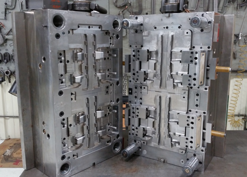
2. Mold Structure Calculations
Determining Cavity and Core Dimensions
The dimensions of the cavity (the hollow space in the mould where the plastic is injected) and core (the part that forms the internal features of the product) are directly related to the final dimensions of the product. Tolerance levels must be carefully considered. For high - precision products, such as optical lenses, the tolerance can be as low as \(\pm0.01\ mm\). To account for the shrinkage of the plastic during cooling, the dimensions of the cavity and core are calculated by adding the shrinkage allowance to the nominal product dimensions. If a product has a length of \(L\) and the shrinkage rate is \(s\), the length of the cavity \(L_{cavity}=L(1 + s)\). For example, if \(L = 50\ mm\) and \(s=0.005\) (0.5% shrinkage rate), then \(L_{cavity}=50\times(1 + 0.005)=50.25\ mm\). This ensures that when the plastic cools and shrinks, the final product dimensions are within the required tolerance.
Calculating the Thickness of Mold Plates
The thickness of the mold plates is crucial for the strength and stability of the mould. Thinner plates may lead to deflection under the high pressure during injection, which can cause uneven wall thickness in the product or even damage to the mould. The thickness \(t\) of a rectangular mold plate can be calculated using the formula \(t=\sqrt{\frac{3Fb^{2}}{E[\sigma]}}\), where \(F\) is the maximum injection pressure force, \(b\) is the length of the unsupported side of the plate, \(E\) is the modulus of elasticity of the mold material (e.g., for steel, \(E = 200\times10^{3}\ MPa\)), and \([\sigma]\) is the allowable stress of the material. A stronger mold material with a higher allowable stress can have a thinner plate for the same injection pressure and plate dimensions, but it's important to balance material cost and performance.
3. Flow and Pressure Calculations
Analyzing the Flow of Molten Plastic in the Mold
The flow of molten plastic in the mold is a complex process that depends on factors such as the geometry of the mold cavity, the viscosity of the plastic, and the injection speed. The flow path should be designed to ensure that the plastic reaches all parts of the cavity evenly. In complex molds with multiple cavities or intricate geometries, flow analysis software can be used to simulate the plastic flow. The velocity of the plastic flow also affects the quality of the product. Too high a velocity can cause jetting, where the plastic shoots through the cavity in a non - uniform manner, leading to defects such as air traps and uneven filling. On the other hand, too low a velocity may result in incomplete filling or long cycle times.
Calculating Injection Pressure and Pressure Drop
Injection pressure is required to force the molten plastic into the mold cavity. The injection pressure \(P_{inj}\) can be calculated using the formula \(P_{inj}=\frac{F_{inj}}{A}\), where \(F_{inj}\) is the injection force and \(A\) is the cross - sectional area of the screw or plunger. The pressure drop \(\Delta P\) along the flow path of the plastic in the mold is influenced by factors like the length and diameter of the runner system, the viscosity of the plastic, and the flow rate. A significant pressure drop can lead to insufficient pressure at the end of the flow path, resulting in incomplete filling. The pressure drop can be calculated using the Hagen - Poiseuille equation for laminar flow (\(\Delta P=\frac{128\mu LQ}{\pi d^{4}}\), where \(\mu\) is the viscosity of the plastic, \(L\) is the length of the flow path, \(Q\) is the volumetric flow rate, and \(d\) is the diameter of the flow channel). Maintaining an appropriate injection pressure and minimizing pressure drop is essential for successful injection moulding.
4. Cooling System Calculations
Importance of an Efficient Cooling System
An efficient cooling system is vital for several reasons. Firstly, it reduces the cycle time of the injection moulding process. By quickly cooling the plastic, the product can be ejected from the mould sooner, allowing for more products to be produced in a given time. Secondly, it improves the quality of the product. Uniform cooling prevents warping, shrinkage, and internal stress in the product. In the production of large plastic panels, for example, non - uniform cooling can cause the panel to warp, making it unusable.
Calculating Cooling Channel Dimensions and Cooling Time
The dimensions of the cooling channels, such as diameter and length, are calculated based on the heat transfer requirements. The heat transfer rate \(Q\) from the plastic to the cooling medium (usually water) can be calculated using the formula \(Q = mc\Delta T\), where \(m\) is the mass of the plastic, \(c\) is the specific heat capacity of the plastic, and \(\Delta T\) is the temperature difference between the plastic and the cooling medium. The diameter \(d\) of the cooling channel is then determined based on the required flow rate of the cooling medium to remove this heat. The cooling time \(t_{cool}\) can be calculated using the formula \(t_{cool}=\frac{\rho Vc\Delta T}{hA\Delta T_{lm}}\), where \(\rho\) is the density of the plastic, \(V\) is the volume of the plastic, \(h\) is the heat transfer coefficient between the plastic and the cooling medium, \(A\) is the surface area of the plastic in contact with the mold, and \(\Delta T_{lm}\) is the log - mean temperature difference between the plastic and the cooling medium. Optimizing these calculations ensures an efficient cooling system.
Yigu Technology's View
As a non - standard plastic metal products custom supplier, Yigu Technology has rich experience in injection mould design calculations. When dealing with different materials, we pay special attention to their unique characteristics. For metal - plastic composites, for example, the difference in thermal expansion coefficients between metals and plastics must be carefully considered in calculations. This ensures that the mould can withstand the stress during the cooling process without cracking or deforming.
To enhance calculation efficiency and accuracy, we advocate the use of advanced simulation software. These tools can quickly analyze complex mould structures and predict potential issues, such as uneven plastic flow or hot spots in the cooling system. By simulating different scenarios in the virtual environment, we can optimize the mould design before actual production, saving both time and resources. Additionally, our team regularly updates knowledge on the latest material properties and industry - standard calculation methods, ensuring that every project benefits from the most current and accurate data.
FAQ
1. What are the most common mistakes in injection mould design calculations?
One of the most prevalent mistakes is incorrect material parameter selection. For example, using the wrong shrinkage rate value for a plastic material can lead to significant dimensional errors in the final product. A miscalculation in the flowability of the plastic can result in improper gate design, causing issues like incomplete filling of the mould cavity. Another common error is overlooking the practical limitations of the mould structure. Designers may calculate ideal dimensions without considering factors such as the strength of the mould material or the available manufacturing processes. To avoid these mistakes, always double - check material data sheets from reliable sources, and conduct thorough feasibility studies on the mould structure during the design phase.
2. How can I improve the accuracy of my injection pressure calculations?
To enhance the accuracy of injection pressure calculations, start by precisely measuring the material properties. Use advanced testing equipment to determine the viscosity of the plastic at different temperatures accurately. Consider the actual situation of the mould, including the complexity of the flow path, the roughness of the mould surface, and any potential obstructions in the runner system. Employing computational fluid dynamics (CFD) software can also provide valuable insights into the plastic flow behavior, allowing for more accurate prediction of the injection pressure required. Additionally, conduct pilot runs with the initial mould design and adjust the pressure calculations based on the observed results.
3. Are there any shortcuts or rules of thumb for quick calculations in injection mould design?
In the preliminary design stage, some rules of thumb can be useful. For example, a common rule of thumb for estimating the injection pressure is that for simple moulds with low - viscosity plastics, the injection pressure can be in the range of 50 - 100 MPa, while for more complex moulds or high - viscosity plastics, it can be 100 - 200 MPa. When calculating the cooling time, a rough estimate is that for every 1 mm of wall thickness, the cooling time is approximately 30 - 60 seconds. However, these are only approximations. They have significant limitations as they do not account for the specific details of the plastic material, the mould geometry, or the production conditions. For accurate results, detailed calculations and simulations are essential.