Introduction
Metal Injection Molding (MIM) is a manufacturing process that combines the design freedom of plastic injection molding with the strength and durability of metal. It produces small, complex metal parts with precision that traditional methods struggle to match.
MIM fills a critical gap. When parts are too complex for machining, too small for casting, or too high-volume for investment casting, MIM offers an economical solution. The process can produce thousands of identical parts with tolerances as tight as ±0.05 mm—all from metal powder that starts as a flowable feedstock.
This guide explains how MIM achieves this precision. You will learn about the materials, the step-by-step process, and the critical parameters that determine success. By the end, you will understand why MIM is the preferred method for complex metal components in medical, aerospace, automotive, and consumer electronics.
What Is Metal Injection Molding?
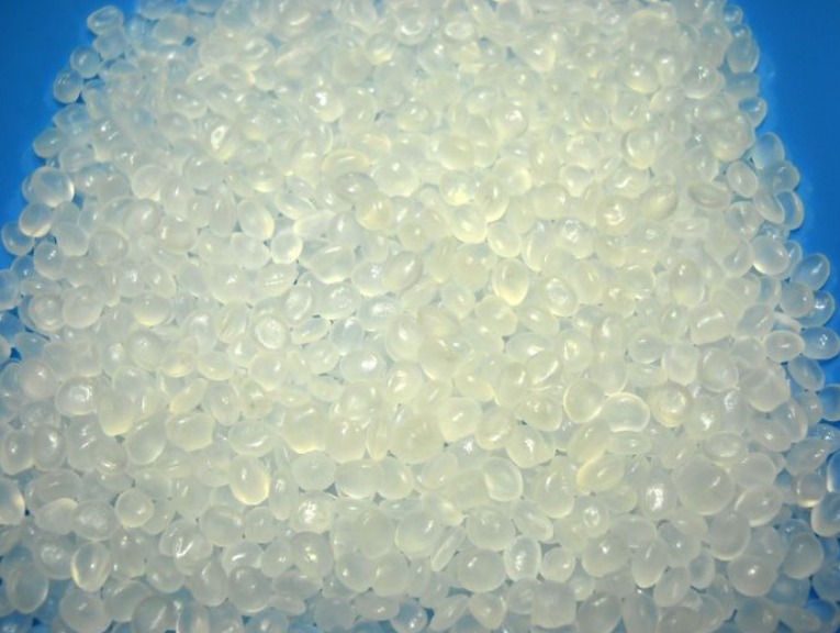
Metal Injection Molding is a manufacturing process that produces high-density metal parts from metal powder mixed with a binder. The mixture—called feedstock—is injected into a mold, then processed to remove the binder and fuse the metal particles.
How Does MIM Compare to Other Processes?
| Process | Best For | Limitations |
|---|---|---|
| MIM | Small, complex, high-volume metal parts | Part size limited (typically <100g); higher tooling cost than machining |
| Investment casting | Larger parts; wider material range | Higher per-part cost for small parts; less design freedom for very complex geometries |
| CNC machining | Low volume; simple to moderate complexity | Material waste; high cost per part at volume |
| Powder metallurgy | Simple shapes; high volume | Limited geometric complexity |
| Plastic injection molding | Plastic parts only | Cannot produce metal components |
Why Choose MIM?
MIM offers distinct advantages:
- Design freedom – Complex geometries, undercuts, thin walls, and internal features
- Precision – Tolerances of ±0.3–0.5% of dimension (as tight as ±0.05 mm)
- Material properties – Near-wrought density (95–99%) and mechanical strength
- Surface finish – As-molded finishes of 1–2 µm Ra; can be polished or plated
- Scalability – Cost-effective from 10,000 to millions of parts
- Material efficiency – Over 95% material utilization; minimal waste
What Materials Are Used in MIM?
MIM works with a wide range of metals. Material selection determines the final part’s properties.
Common Metal Powders
| Material | Key Properties | Typical Applications |
|---|---|---|
| Stainless Steel (316L, 17-4PH) | Corrosion resistance; high strength; biocompatible | Medical devices, surgical instruments, electronics, automotive |
| Low-Alloy Steel (Fe-2Ni, Fe-8Ni) | High strength; magnetic properties; cost-effective | Magnetic components, engine parts, structural components |
| Titanium (Ti-6Al-4V) | High strength-to-weight ratio; excellent corrosion resistance; biocompatible | Aerospace components, medical implants, dental devices |
| Tungsten Alloys | High density; high melting point | Counterweights, heat sinks, radiation shielding |
| Copper Alloys | Electrical conductivity; thermal conductivity | Heat sinks, electrical contacts |
| Tool Steels | Wear resistance; hardness | Cutting tools, wear components |
Metal Powder Characteristics
Powder particle size and shape directly affect MIM results:
| Parameter | Typical Range | Impact |
|---|---|---|
| Particle size | 0.5–20 µm | Finer powders sinter better but cost more; coarser powders require higher sintering temperatures |
| Particle shape | Spherical preferred | Spherical powders flow better; irregular shapes increase viscosity |
| Purity | >99% | Impurities affect mechanical properties and sintering behavior |
Binder Systems
The binder enables the metal powder to flow like plastic during injection. It must provide:
| Function | Requirement |
|---|---|
| Flowability | Low viscosity for complete mold filling |
| Shape retention | Enough strength to hold green part shape |
| Lubrication | Reduce friction during injection |
| Removability | Clean decomposition without residue |
Common binder types:
- Wax-based – Easy removal; good flow; common for general applications
- Thermoplastic – Higher strength; used for complex geometries
- Water-soluble – Environmental benefits; specific debinding processes
How Does the MIM Process Achieve Precision?
MIM precision comes from careful control at each stage. The process transforms metal powder into finished parts through four main steps.
Stage 1: Mixing – The Foundation of Precision
Mixing combines metal powder and binder into a homogeneous feedstock. This step determines consistency across every subsequent stage.
Critical parameters:
- Powder-to-binder ratio – Typically 55–65% powder by volume
- Mixing temperature – Above binder melting point
- Mixing time – Sufficient for complete dispersion
- Uniformity – No agglomerates or binder-rich zones
Why mixing matters: If the binder content is too high, the part shrinks excessively during sintering, causing dimensional errors. If binder content is too low, the feedstock lacks flowability, leading to incomplete filling or voids. Inconsistent mixing creates property variations within the same batch.
Real-world example: A manufacturer producing 17-4PH stainless steel components for medical devices experienced dimensional variation of ±0.15 mm across batches. After implementing automated mixing with real-time viscosity monitoring, batch-to-batch variation dropped to ±0.05 mm.
Stage 2: Molding – Shaping with Extreme Precision
The molding stage is where the part takes shape. The feedstock is injected into a mold cavity under high pressure—typically 30–150 MPa (4,000–22,000 psi).
Mold design considerations:
- Gating – Must ensure complete filling without excessive shear
- Venting – Air must escape to prevent voids
- Draft angles – 0.5–1.5° for ejection
- Tolerances – Mold tolerances as tight as ±0.01 mm
- Surface finish – Transfers directly to the green part
What MIM molds achieve:
- Complex geometries including thin walls (down to 0.2 mm)
- Fine features (holes as small as 0.1 mm)
- Undercuts and threads
- Multiple cavities for high throughput
Green part strength: The molded part—called a “green part”—has enough strength for handling but is still fragile. It must be processed without damage.
Stage 3: Debinding – Removing the Binder
Debinding removes the binder from the green part, leaving a porous metal “brown part” ready for sintering.
Debinding methods:
| Method | Process | Advantages | Challenges |
|---|---|---|---|
| Thermal debinding | Heat to decompose binder | Simple; no chemicals | Slow; risk of distortion |
| Solvent debinding | Dissolve binder in solvent | Faster; less thermal stress | Chemical handling; waste disposal |
| Catalytic debinding | Chemical reaction removes binder | Fast; clean; minimal distortion | Specialized equipment; material-specific |
Why debinding affects precision:
- Too fast – Binder removal causes internal stress; parts warp or crack
- Too slow – Extended cycle time; potential contamination
- Uneven removal – Dimensional variation; residual binder affects sintering
Critical controls:
- Heating rate (typically 1–5°C per minute)
- Temperature profile
- Atmosphere (air, nitrogen, or vacuum)
- Time (hours to days depending on part size)
Real-world example: A manufacturer of titanium alloy dental implants experienced cracking during debinding. Analysis showed the heating rate was too high—binder gas expansion created internal pressure. Reducing the rate from 5°C/min to 2°C/min eliminated cracks entirely.
Stage 4: Sintering – Achieving High-Density Precision
Sintering is the final step. The brown part is heated to a temperature below the metal’s melting point—typically 70–90% of the melting temperature—causing metal particles to bond through diffusion.
What happens during sintering:
- Initial stage – Particle necks form; density increases
- Intermediate stage – Pores close; density reaches 90–95%
- Final stage – Full densification; near-theoretical density (95–99%)
Critical parameters:
| Parameter | Impact on Precision |
|---|---|
| Sintering temperature | Too low = insufficient density; too high = excessive shrinkage or melting |
| Sintering time | Too short = incomplete bonding; too long = grain growth; property changes |
| Atmosphere | Vacuum, hydrogen, or nitrogen affects oxidation and surface finish |
| Cooling rate | Affects microstructure, hardness, and dimensional stability |
Shrinkage control: MIM parts shrink 15–20% linearly during sintering. This shrinkage is predictable—typically ±0.3–0.5% variation—but must be accounted for in mold design. Complex parts may shrink differently in different directions (anisotropic shrinkage).
Real-world example: A manufacturer producing stainless steel surgical instrument components achieved consistent shrinkage by controlling sintering atmosphere. Switching from nitrogen to hydrogen atmosphere reduced oxidation and improved dimensional repeatability from ±0.10 mm to ±0.04 mm.
How Do You Design Parts for MIM?
Designing for MIM requires understanding the process’s capabilities and constraints.
Design Guidelines
| Feature | Recommendation | Why |
|---|---|---|
| Wall thickness | 0.5–10 mm; uniform preferred | Uniform cooling and shrinkage |
| Ribs | Thickness ≤ 0.6× wall thickness | Prevent sink marks |
| Holes | Minimum diameter 0.2 mm | Mold filling; ejection |
| Corners | Radius ≥ 0.25 mm | Reduce stress concentration |
| Draft | 0.5–1.5° | Ejection without damage |
| Undercuts | Possible but may increase tooling cost | Require slides or lifters |
Tolerances
MIM achieves tighter tolerances than many competing processes:
| Part Size | Typical MIM Tolerance | Precision MIM Tolerance |
|---|---|---|
| <10 mm | ±0.05 mm | ±0.02 mm |
| 10–25 mm | ±0.08 mm | ±0.03 mm |
| 25–50 mm | ±0.12 mm | ±0.05 mm |
| >50 mm | ±0.3–0.5% | ±0.2–0.3% |
Surface Finish
As-sintered surface finish: 1–3 µm Ra
Post-processing options:
- Tumbling/polishing – 0.2–0.5 µm Ra
- Electropolishing – Smooth, bright finish
- Plating/coating – Additional corrosion or wear resistance
What Are the Applications of MIM?
MIM serves industries where precision, complexity, and volume intersect.
Medical and Dental
| Application | Material | Requirements |
|---|---|---|
| Surgical instruments | 316L, 17-4PH | Corrosion resistance; sterilization compatibility; precision |
| Orthopedic implants | Ti-6Al-4V | Biocompatibility; strength; osseointegration |
| Dental components | Ti, stainless steel | Precision fit; biocompatibility |
| Biopsy tools | 316L | Miniature size; complex geometry |
Case example: A medical device company needed a laparoscopic instrument with internal channels for fluid flow and cable routing. Traditional machining would require multiple components assembled. MIM produced the part as a single component with integrated channels, reducing assembly cost by 40% and eliminating potential failure points.
Automotive
| Application | Material | Requirements |
|---|---|---|
| Fuel system components | 316L, 17-4PH | Chemical resistance; pressure tightness |
| Turbocharger components | Fe-2Ni, Fe-8Ni | High temperature; strength |
| Lock mechanisms | Low-alloy steel | Wear resistance; precision |
| Sensor housings | Stainless steel | Corrosion resistance; magnetic properties |
Consumer Electronics
| Application | Material | Requirements |
|---|---|---|
| Smartphone camera rings | 316L | Aesthetic; wear resistance |
| Watch cases and buckles | 316L, Ti | Aesthetic; corrosion resistance |
| Hinge mechanisms | 17-4PH | Strength; precision |
| Connector pins | Cu alloys | Electrical conductivity |
Aerospace and Defense
| Application | Material | Requirements |
|---|---|---|
| Firearm components | 17-4PH, tool steel | Strength; wear resistance |
| Sensor housings | Ti, stainless | Lightweight; corrosion resistance |
| Control mechanisms | Stainless steel | Precision; reliability |
What Are the Advantages and Limitations of MIM?
Advantages
| Advantage | Explanation |
|---|---|
| Design freedom | Complex geometries impossible with machining |
| Precision | Tolerances as tight as ±0.05 mm |
| Material efficiency | >95% material utilization; minimal waste |
| High volumes | Economical from 10,000 to millions of parts |
| Material properties | Near-wrought strength and density |
| Surface finish | Good as-sintered finish; post-processing options |
| Multiple materials | Wide range of alloys available |
Limitations
| Limitation | Explanation |
|---|---|
| Part size | Typically under 100g; larger parts possible but less economical |
| Tooling cost | $10,000–$50,000+; requires high volumes to amortize |
| Lead time | 12–20 weeks for tooling and process development |
| Shrinkage variation | 15–20% predictable but requires compensation in mold design |
| Material cost | Fine metal powders cost more than conventional metal stock |
| Not for very large parts | Size and weight limitations |
How Do You Ensure Quality in MIM?
Quality control in MIM covers every stage of production.
In-Process Controls
| Stage | Controls |
|---|---|
| Raw materials | Powder particle size; binder composition; batch certification |
| Mixing | Torque; temperature; time; homogeneity testing |
| Molding | Shot weight; injection parameters; visual inspection of green parts |
| Debinding | Weight loss monitoring; temperature profile; atmosphere |
| Sintering | Temperature; time; atmosphere; shrinkage monitoring |
Final Part Inspection
- Dimensional – CMM, optical measurement
- Mechanical – Tensile, hardness, fatigue testing
- Microstructure – Metallography; density measurement
- Surface finish – Profilometry; visual inspection
Common Defects and Solutions
| Defect | Likely Cause | Solution |
|---|---|---|
| Warpage | Uneven debinding or sintering | Control heating rate; optimize part orientation |
| Voids | Binder residue; inadequate mixing | Improve debinding; extend mixing time |
| Surface cracks | Rapid debinding; thermal stress | Slower heating rate; improve atmosphere |
| Dimensional variation | Powder variation; inconsistent shrinkage | Control powder source; stabilize process |
| Low density | Sintering temperature too low | Increase temperature; extend time |
Conclusion
Metal Injection Molding (MIM) is a precision manufacturing process that produces complex metal parts with near-wrought properties. The process achieves its precision through careful control at four critical stages:
- Mixing – Homogeneous feedstock with precise powder-to-binder ratio
- Molding – High-precision molds and controlled injection parameters
- Debinding – Controlled binder removal to prevent distortion
- Sintering – Precise temperature, time, and atmosphere for consistent shrinkage
MIM excels for small, complex parts where traditional manufacturing methods are impractical. It serves medical, automotive, electronics, and aerospace industries with parts that combine geometric complexity with metal strength. When volumes justify the tooling investment, MIM delivers consistent, high-precision components that meet demanding specifications.
Frequently Asked Questions (FAQ)
What are the common metal powders used in MIM?
Common metal powders include stainless steel (316L, 17-4PH) for corrosion resistance, low-alloy steel for magnetic and structural components, titanium alloys for high strength-to-weight and biocompatibility, tungsten alloys for high density, and copper alloys for electrical and thermal conductivity. Material selection depends on the application’s mechanical, chemical, and environmental requirements.
How does MIM compare to traditional manufacturing in terms of precision?
MIM achieves significantly higher precision for complex, small parts. Typical tolerances are ±0.3–0.5% of dimension, which translates to ±0.05 mm for a 10 mm part. Traditional methods like investment casting typically achieve ±0.5–1.0%, while machining can achieve higher precision but at much higher cost for complex geometries. MIM fills the gap between high-precision machining and high-volume casting.
What are the main challenges in the MIM process for maintaining precision?
The main challenges are controlling shrinkage (15–20% linear) during sintering, preventing distortion during debinding, and maintaining material consistency from batch to batch. Each stage requires precise control: powder-to-binder ratio in mixing, temperature and pressure in molding, heating rate in debinding, and temperature uniformity in sintering. Advanced process controls and statistical methods help maintain consistency.
What part sizes are suitable for MIM?
MIM is most economical for parts weighing under 100 grams. Parts from 0.1 to 100 grams are typical. Larger parts are possible but become less cost-effective compared to casting or machining. The process excels at small, intricate components—parts that would be difficult or impossible to machine economically.
How long does MIM tooling take and how much does it cost?
MIM tooling typically takes 12–20 weeks from design to first samples. Tooling cost ranges from $10,000 to $50,000+ depending on complexity, number of cavities, and required tolerances. Because of this investment, MIM is most economical for production volumes above 10,000–50,000 parts annually, though lower volumes may be justified for complex parts that cannot be made by other methods.
Contact Yigu Technology for Custom Manufacturing
At Yigu Technology, we specialize in Metal Injection Molding (MIM) for high-precision components across medical, automotive, electronics, and industrial applications. Our expertise spans material selection, mold design, process optimization, and quality control.
Our MIM capabilities include:
- Wide material range – Stainless steel, titanium, low-alloy steel, copper alloys
- Precision molds – Complex geometries with tight tolerances
- Process control – Advanced debinding and sintering with atmosphere control
- Quality assurance – CMM inspection; mechanical testing; metallography
- Volume flexibility – From pilot runs to high-volume production
We understand that MIM requires precision at every stage. Our experienced team works with you from design to delivery to ensure your components meet specifications.
Contact us today to discuss your MIM project. Let our expertise help you achieve the precision your application demands.