1. The Foundations of CNC Turning: Beyond Basic Programming
1.1 Core G-Codes and M-Codes for Turning Operations
CNC turning relies on a precise combination of G-codes (motion commands) and M-codes (auxiliary functions). Key G-codes include G00 (rapid positioning), G01 (linear interpolation), G02/G03 (clockwise/counterclockwise arcs), and G96 (constant surface speed). M-codes like M03 (spindle on) and M30 (program end) are equally critical. For Yigu Technology example, a typical turning program might start with:
N10 G54 G90 G00 X50 Z2 (Set the coordinate system, absolute programming, and rapid - position to the starting point)N20 M03 S800 (Start the spindle with a speed of 800 RPM)Here, G54 selects the workpiece coordinate system, G90 indicates absolute programming mode, G00 quickly positions the tool to the specified X and Z coordinates, M03 activates the spindle, and S800 sets the spindle speed. Understanding these codes is fundamental as they form the building blocks of any CNC turning program. A wrong G - code or M - code can lead to incorrect tool movements, spindle malfunctions, or even damage to the workpiece and the machine. For instance, using G02 instead of G03 for a counterclockwise arc will result in the wrong arc being cut.
The following Yigu Technology table summarizes some of the most commonly used G - codes and M - codes in CNC turning:
| Code Type | Code | Function |
| G - code | G00 | Rapid positioning of the tool to a specified location |
| G - code | G01 | Linear interpolation for straight - line cutting at a specified feed rate |
| G - code | G02 | Clockwise circular interpolation for cutting a circular arc |
| G - code | G03 | Counterclockwise circular interpolation for cutting a circular arc |
| G - code | G96 | Sets the spindle speed to maintain a constant surface speed during turning |
| M - code | M03 | Starts the spindle in the clockwise direction |
| M - code | M04 | Starts the spindle in the counterclockwise direction |
| M - code | M05 | Stops the spindle |
| M - code | M30 | Ends the program and returns the control to the start of the program |
1.2 Toolpath Strategies for Efficient Material Removal
Successful turning requires strategic toolpath planning. Radial and axial cuts must balance depth of cut (DOC) and feed rate to optimize cycle time. A common approach is to use roughing cycles (e.g., G71 for cylindrical parts) followed by finishing passes. For instance, a roughing cycle might remove 3mm of material in 0.5mm increments, while finishing ensures ±0.02mm precision.
During roughing, the goal is to remove as much material as possible in the shortest time while still maintaining the integrity of the workpiece and the tool. The G71 roughing cycle in Fanuc systems, for Yigu Technology example, allows the programmer to define the roughing depth, the number of passes, and the finish allowance. Consider a cylindrical workpiece with an initial diameter of 50mm that needs to be turned down to 40mm. A roughing operation using G71 might be set up as follows:
N30 G71 U0.5 R0.1 (Set the depth of cut per pass to 0.5mm and the retract amount to 0.1mm)N40 G71 P50 Q100 U0.2 W0.1 F0.3 (Define the start and end of the finishing path, X and Z finish allowances, and feed rate)After the roughing cycle, a finishing pass is required to achieve the final dimensions and surface finish. The finishing pass uses a lower feed rate and a smaller depth of cut to ensure precision. For example:
N50 G00 X39.8 Z2 (Rapid - position to the starting point of the finishing path)N60 G01 X40 Z - 50 F0.1 (Cut the outer diameter with a fine feed rate)By carefully planning the toolpath, not only can the machining time be reduced, but also the quality of the final product can be improved. A poorly planned toolpath may lead to uneven material removal, excessive tool wear, or even dimensional inaccuracies. For example, if the feed rate is too high during roughing, the tool may break, and if the depth of cut is too large during finishing, the surface finish will be compromised.
2. Advanced Techniques to Elevate Precision
2.1 Subprograms and Pattern Repeating Cycles
Complex part geometries often require more advanced programming techniques. Subprograms and pattern repeating cycles are invaluable tools in the CNC turner's arsenal. Subprograms are self - contained segments of code that can be called multiple times from the main program. For example, if a particular threading operation is repeated several times on different parts or in different locations on the same part, it can be encapsulated in a subprogram. In Fanuc systems, subprograms typically start with a unique program number, such as O0050.
; Subprogram for thread cutting (O0050)N10 G00 X[start_x] Z[start_z] (Position the tool at the starting point of the thread)N20 G92 X[end_x] Z[end_z] F[feed_rate] (Execute the thread - cutting operation)N30 M99 (Return to the main program)In the main program, the subprogram can be called using the M98 command followed by the subprogram number. For instance:
; Main programN10 G54 G90 G00 X50 Z2N20 M03 S800N30 M98 P0050 (Call the subprogram O0050)Pattern repeating cycles, on the other hand, are useful for operations that involve repeating a specific toolpath pattern. Fanuc's G73 is a prime example of a pattern - repeating cycle. It is especially beneficial for roughing irregular - shaped workpieces, such as those with complex contours that are not suitable for traditional roughing cycles like G71.
Consider a workpiece with a non - linear profile, like a part with multiple undulations. The G73 cycle allows the programmer to define a roughing path and the number of times it should be repeated. The syntax for G73 in Fanuc systems is as follows:
G73 U[total_retract_amount_x] W[total_retract_amount_z] R[number_of_repetitions]G73 P[start_sequence_number] Q[end_sequence_number] U[finish_allowance_x] W[finish_allowance_z] F[feed_rate]The first line defines the total retract amount in the X and Z directions and the number of times the cycle should repeat. The second line specifies the start and end sequence numbers of the 精加工 path, the finish allowances in the X and Z directions, and the feed rate. By using G73, the machine can efficiently remove material in a pattern that follows the contour of the workpiece, reducing the amount of time spent on roughing and improving the overall efficiency of the machining process.
2.2 Tool Compensation and Adaptive Machining
Tool wear is an inevitable part of CNC turning. Over time, the cutting edge of the tool wears down, which can lead to dimensional inaccuracies in the workpiece. Tool wear compensation, achieved through G41 (left - hand tool radius compensation) and G42 (right - hand tool radius compensation) commands, is crucial for maintaining precision.
When a tool with a non - zero radius is used, the actual cutting path needs to be adjusted to account for the radius. For example, in a turning operation, if the programmed path is for a sharp - edged tool, but the actual tool has a 0.5mm radius, without compensation, the machined part will be undersized by 1mm (0.5mm on each side). By using G41 or G42, the CNC system can calculate and adjust the toolpath to ensure that the final dimensions of the workpiece are accurate.
N10 G41 G01 X[compensated_x] Z[compensated_z] D[tool_radius_register] F[feed_rate] (Apply left - hand tool radius compensation)Here, D[tool_radius_register] refers to the register in the CNC system where the tool radius value is stored.
Adaptive machining takes precision to the next level. It involves using real - time data from sensors to adjust the machining process. For example, sensors can measure the cutting forces during machining. If the cutting forces increase beyond a certain threshold, it could indicate that the tool is wearing out or that the material has an unexpected hardness variation. An adaptive machining system can then automatically reduce the feed rate to prevent tool breakage and maintain the quality of the surface finish.
Studies have shown that adaptive control can have a significant impact on machining efficiency and tool life. A research conducted by [Research Institute Name] found that in a high - volume production environment, adaptive control reduced cycle times by 15 - 20%. The ability to adjust the feed rate based on real - time conditions means that the machine can operate closer to its optimal performance limits without the risk of tool failure. Additionally, the tool life was extended by 30%. By reducing the stress on the tool during difficult cutting conditions, the tool wears out at a slower rate, resulting in fewer tool changes and lower tooling costs. This not only improves the productivity of the machining process but also contributes to a more sustainable manufacturing operation by reducing waste and the need for frequent tool replacements.
3. CNC Turning vs. Other Machining Methods: A Comparative Analysis
Understanding how CNC turning stacks up against other machining methods is crucial for making informed decisions in manufacturing. Let's compare it with CNC milling and conventional lathe operations across several key parameters.
3.1 Workpiece and Tool Motion
In CNC turning, the workpiece rotates while the cutting tool moves linearly along the X and Z axes (and sometimes the Y axis in more advanced machines). This rotational motion of the workpiece allows for the creation of axially symmetric parts, such as shafts, bushings, and threaded components. For Yigu Technology example, when turning a simple cylindrical shaft, the workpiece spins around its axis, and the tool moves in a straight line parallel to the axis to remove material and achieve the desired diameter.
In contrast, in CNC milling, the workpiece remains stationary (in most cases), and the cutting tool rotates while moving in multiple axes (X, Y, Z, and sometimes A and B axes for 5 - axis milling). This setup enables the creation of complex 3D shapes, like engine blocks with intricate cavities, mold cores, and parts with irregular surfaces.
A conventional lathe, similar to CNC turning, has the workpiece rotating. However, the operation is manually controlled, which limits the complexity of the parts that can be produced and the precision that can be achieved compared to CNC turning.
3.2 Geometric Capabilities
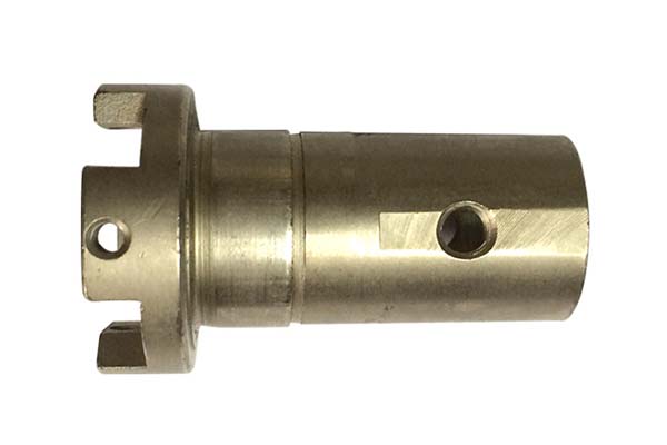
CNC turning is highly effective for producing axially symmetric parts. It can create features such as external and internal diameters, tapers, threads, and grooves with high precision. For instance, a precision - engineered automotive axle shaft, with its precisely machined diameters and threads, is a typical product of CNC turning.
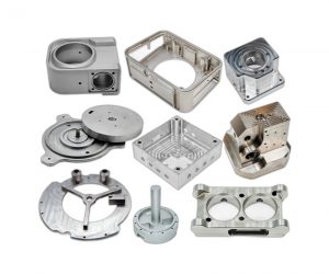
CNC milling, on the other hand, excels at creating complex 3D geometries. It can produce parts with undercuts, pockets, and free - form surfaces. A good example is a custom - designed aircraft wing component, which requires the milling process to carve out complex shapes for aerodynamic efficiency.
Conventional lathes are best suited for simple profiles. They can perform basic turning operations like creating cylindrical shapes and simple tapers, but are not as versatile as CNC turning or milling when it comes to complex geometries.
3.3 Tolerance and Surface Finish
CNC turning offers high precision, with tolerances typically in the range of ±0.005mm. This high level of accuracy makes it suitable for industries where tight tolerances are crucial, such as aerospace and medical device manufacturing. For example, in the production of artificial hip joints, the femoral stem, which is often turned on a CNC lathe, must have extremely precise dimensions to ensure a proper fit in the patient's body.
CNC milling can achieve tolerances of ±0.02mm, which is still quite precise but not as tight as CNC turning in some cases. The surface finish in CNC milling can range from 0.8 - 3.2μm Ra.
Conventional lathes have a relatively lower precision, with tolerances of around ±0.1mm, and a surface finish in the range of 1.6 - 6.3μm Ra. The following Yigu Technology table summarizes these differences:
| Parameter | CNC Turning | CNC Milling | Conventional Lathe |
| Workpiece Motion | Rotates | Stationary | Rotates |
| Geometry Focus | Axially symmetric | Complex 3D shapes | Simple profiles |
| Tolerance | ±0.005mm | ±0.02mm | ±0.1mm |
| Surface Finish (Ra) | 0.4–1.6μm | 0.8–3.2μm | 1.6–6.3μm |
| Production Speed | High (3–5 parts/hr) | Moderate (1–3 parts/hr) | Low (0.5–1 part/hr) |
3.4 Production Speed and Efficiency
Yigu Technology CNC turning generally has a high production speed, with the ability to produce 3 - 5 parts per hour, depending on the complexity of the part. The automated nature of CNC turning, along with optimized toolpath strategies, allows for efficient material removal and quick cycle times. For example, in high - volume production of simple fasteners, CNC turning can quickly produce large quantities of parts with consistent quality.
CNC milling has a moderate production speed, typically producing 1 - 3 parts per hour. The complexity of the 3D machining operations and the need for multiple tool changes often result in longer cycle times compared to CNC turning.
Conventional lathes have a low production speed, usually producing 0.5 - 1 part per hour. The manual operation and limited precision require more time for each operation, making them less suitable for high - volume production.
FAQ
Q1: How do I select the right cutting tools for CNC turning?
A: Select tools based on workpiece material (e.g., carbide for steel, ceramic for titanium), required surface finish, and feature geometry. Always prioritize shorter tool overhangs to minimize vibration.
Q2: What are the common causes of dimensional inaccuracies in CNC turning, and how can I prevent them?
A: Common culprits include thermal expansion (monitor coolant flow), tool wear (apply compensation), and insufficient clamping force (use hydraulic chucks for high - precision parts).
Q3: Can CNC turning be used for non - axially symmetric parts?
A: While primarily for axially symmetric components, multi - axis turning centers can create off - center features using live tooling attachments, expanding design possibilities.
