thermal molds are a must for shaping those heat-sensitive materials like waxes, but let’s face it, buying commercial molds can break the bank. we’ll walk you through how to make your own sturdy thermal injection molds with just some basic tools and budget-friendly supplies. We’ll cover everything from designing the mold base, creating the cavity, installing the heating elements, and more. Just follow our step-by-step plan, and in no time, you’ll be ready to roll!
Choosing Mold Materials
Introduction
When it comes to building high-quality thermal injection molds on a shoestring budget, choosing the right mold materials is crucial. The materials you select will determine the durability, precision, and overall performance of your molds. In this section, we will explore key factors to consider when choosing mold materials.
Factors to Consider
- Cost: Since you are working with a limited budget, it's important to choose materials that are cost-effective. Look for materials that offer a good balance between affordability and quality. Common options include steel alloys, aluminum, and various grades of plastic.
- Durability: Your molds should be able to withstand the rigors of repeated injections over an extended period. Steel alloys, such as P20 or H13, are known for their excellent durability and resistance to wear. If you're working on a smaller scale or with less demanding materials, aluminum can be a more cost-effective option.
- Thermal Conductivity: Efficient heat transfer is essential for proper molding. Consider the thermal conductivity of the material you choose to ensure it can effectively dissipate heat during the injection process. Steel alloys generally have better thermal conductivity than aluminum and plastics.
- Corrosion Resistance: Depending on the type of material being injected and the environment in which the molds will be used, corrosion resistance may be a crucial factor. Stainless steel alloys, such as 420 or 316, offer excellent resistance to corrosion, making them suitable for demanding applications.
- Surface Finish: The surface finish of your molds can impact the quality of the final product. Choose materials that allow for smooth finishes, reducing the need for additional post-processing. Steel alloys typically offer better surface finishes compared to aluminum or plastics.
- Machinability: Consider the ease of machining the material. Some materials may require specialized equipment or techniques, which can add to the overall cost. Aluminum is generally easier to machine compared to steel alloys, making it a popular choice for budget-conscious mold builders.
Choosing the right mold materials is a crucial step in building high-quality thermal injection molds on a limited budget. Consider factors such as cost, durability, thermal conductivity, corrosion resistance, surface finish, and machinability when making your selection. By carefully analyzing these factors and finding the right balance, you can ensure the success of your mold-building project without compromising on quality.
Drafting the Mold Base
Introduction
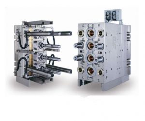
Drafting the mold base is an essential step in the process of building high-quality thermal injection molds. The mold base provides the foundation for the mold and determines its overall structure and functionality. In this section, we will discuss key considerations and best practices for drafting the mold base.
Design Considerations
- Part Geometry: Analyze the geometry of the part that will be molded and design the mold base accordingly. Consider factors such as part complexity, undercuts, and the need for slides or lifters. Ensure that the mold base design allows for efficient and accurate molding of the desired part.
- Parting Line: Determine the parting line, which is the line where the two halves of the mold separate. The mold base should be designed to facilitate easy part removal and minimize any damage or distortion to the molded part. Carefully consider the parting line location to ensure optimal mold functionality.
- Gate and Runner System: Plan the gate and runner system that will allow the molten material to flow into the mold cavity. The mold base design should incorporate channels and passages for the proper distribution of the material. Consider factors such as gate location, runner dimensions, and material flow dynamics.
- Cooling System: Efficient cooling is crucial for maintaining consistent part quality and cycle times. Design the mold base to accommodate cooling channels that allow for optimal heat dissipation. Consider the placement and size of the cooling channels to ensure uniform cooling throughout the mold.
- Ejection System: Determine the ejection system that will facilitate the removal of the molded part from the mold. The mold base should incorporate features such as ejector pins, slides, or lifters as required by the part geometry. Ensure that the ejection system is robust and can withstand repeated use.
Best Practices
- Standardization: Utilize standardized mold base components whenever possible to reduce costs and save time. Many suppliers offer pre-made mold bases that can be customized to fit your specific needs. Standardization also allows for easier maintenance and repair of the molds in the future.
- Design for Manufacturability: Consider the manufacturing capabilities and limitations of your equipment when drafting the mold base.Ensure that the design is feasible and can be manufactured with the resources available to you. Avoid complex designs that require specialized machining or costly modifications.
- Accuracy and Precision: Pay close attention to the dimensions and tolerances of the mold base. Accuracy and precision are essential for ensuring proper alignment and functionality of the mold components. Use CAD software or precision machining techniques to achieve the desired level of accuracy.
- Modularity: Design the mold base in a modular fashion, allowing for easy replacement or modification of individual components. This approach improves maintenance and repairability, reducing downtime and costs associated with mold repairs.
- Consider Future Needs: Anticipate potential future requirements, such as changes in part design or material, and design the mold base with flexibility in mind. Incorporate features that allow for easy adaptation or modification without the need for a complete redesign.
Drafting the mold base is a critical step in building high-quality thermal injection molds. Consider factors such as part geometry, parting line, gate and runner system, cooling system, and ejection system during the design process. Follow best practices such as standardization, design for manufacturability, accuracy and precision, modularity, and consideration of future needs. By implementing these considerations and practices, you can ensure the construction of a mold base that meets your budget constraints while delivering superior performance and quality.
Cutting the Mold Cavity
Introduction
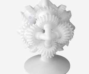
Once the mold base has been drafted, the next crucial step in building high-quality thermal injection molds is cutting the mold cavity. The mold cavity defines the shape and dimensions of the final molded part. In this section, we will discuss the process and considerations involved in cutting the mold cavity.
Process Overview
- Preparation: Before cutting the mold cavity, ensure that the mold base is clean and free from any debris or contaminants. Use precision measuring tools to verify the accuracy of the mold base dimensions. Prepare the cutting tools, such as milling machines, CNC equipment, or EDM (Electrical Discharge Machining) machines, depending on the complexity of the mold design.
- Toolpath Planning: Analyze the mold design and determine the most efficient toolpath for cutting the mold cavity. Consider factors such as part geometry, undercuts, and the desired surface finish. Plan the toolpath to minimize material waste and optimize cutting efficiency.
- Rough Cutting: Begin by rough cutting the mold cavity, removing the majority of the material. This process can be done using a milling machine or other suitable cutting equipment. Ensure that the rough cut maintains a safe distance from the final dimensions to allow for finishing operations.
- Finishing: Once the rough cut is complete, proceed with the finishing operations. This involves using finer cutting tools or techniques to achieve the desired dimensional accuracy and surface finish. Pay close attention to critical areas, such as tight tolerances or complex geometries, to ensure their proper formation.
- Quality Control: Regularly inspect the mold cavity during the cutting process to ensure accuracy and quality. Use measurement tools such as calipers, micrometers, or coordinate measuring machines to verify that the dimensions meet the required specifications. Make any necessary adjustments or corrections as needed.
- Surface Treatment: Depending on the material and application, consider applying surface treatments to the mold cavity. Treatments such as polishing, coating, or texturing can enhance the final part's appearance, functionality, and mold release properties. Follow best practices and industry standards for surface treatments.
Considerations
- Material Selection: Choose cutting tools suitable for the material being used for the mold cavity. Different materials may require specific tooling and cutting techniques to achieve optimal results. Consider factors such as hardness, machinability, and thermal conductivity when selecting cutting tools.
- Tool Life: Monitor and manage the tool life during the cutting process. Cutting tools can wear out over time, leading to decreased accuracy and surface quality. Replace or recondition worn tools to maintain consistent results throughout the cutting process.
- Chip Management: Proper chip management is essential to prevent chip buildup and ensure efficient cutting. Use appropriate cutting fluids or lubricants to facilitate chip evacuation and reduce tool wear. Clear away chips regularly to avoid interference with the cutting process.
- Tool Path Optimization: Optimize the toolpath to minimize cutting time and maximize efficiency. Consider using CAM (Computer-Aided Manufacturing) software to generate optimized toolpaths based on the mold design. This approach can help reduce material waste and improve overall productivity.
- Workholding: Ensure secure and stable workholding during the cutting process. Proper clamping or fixturing is essential to prevent movement or vibrations that can affect the accuracy of the mold cavity. Use suitable workholding solutions based on the size, shape, and material of the mold base.
Cutting the mold cavity is a critical step in building high-quality thermal injection molds. Follow a systematic process that involves preparation, toolpath planning, rough cutting, finishing, quality control, and surface treatment. Consider factors such as material selection, tool life, chip management, tool path optimization, and workholding to ensure accurate and efficient cutting. By adhering to these considerations and best practices, you can achieve precise mold cavities that meet the required specifications for your thermal injection molding project.
Installing Thermal Gates & Runners
Introduction
Installing thermal gates and runners is an essential part of building high-quality thermal injection molds. The gate and runner system ensures the proper flow of molten material into the mold cavity, allowing for consistent and uniform part formation. In this section, we will discuss the process and considerations involved in installing thermal gates and runners.
Process Overview
- Gating Design: Analyze the part geometry, material properties, and molding requirements to determine the most suitable gating design. Consider factors such as gate location, gate type (e.g., edge gate, tunnel gate, or hot runner system), and the number of gates required. Design the gating system to facilitateadequate material flow and minimize potential defects, such as flow lines or air traps.
- Gate and Runner Fabrication: Fabricate the gates and runners according to the gating design. Depending on the complexity of the design, this may involve machining, EDM, or other fabrication processes. Use materials that can withstand the high temperatures and pressures involved in the injection molding process, such as steel alloys or specialized polymers for hot runner systems.
- Runner Installation: Install the runners onto the mold base, ensuring proper alignment and secure attachment. Use suitable fasteners or clamping mechanisms to hold the runners in place. Pay attention to the flow path and ensure that it allows for efficient material distribution to the individual cavities.
- Gate Installation: Install the gates at the designated locations on the mold cavity. Ensure that the gates are properly aligned with the runners and allow for smooth material flow. Use appropriate techniques, such as welding or insert molding, to secure the gates in place and ensure a leak-free connection.
- Runner and Gate Surface Treatment: Consider applying surface treatments to the runners and gates to enhance their performance and durability. Treatments such as polishing or coating can improve material flow, reduce friction, and minimize the risk of material sticking or clogging.
- Testing and Optimization: Conduct thorough testing of the gate and runner system to ensure proper functionality and material flow. Monitor the injection process and observe the part formation to identify any issues or areas for optimization. Make necessary adjustments, such as gate size or location, to achieve the desired molding results.
Considerations
- Material Compatibility: Select gate and runner materials that are compatible with the molten material being injected. Consider factors such as temperature resistance, chemical compatibility, and wear resistance. Consult material suppliers or experts if necessary to ensure proper material selection.
- Flow Analysis: Conduct flow analysis simulations or calculations to optimize the design of the gate and runner system. This analysis can help identify potential flow-related issues, such as excessive pressure drop or uneven material distribution. Adjust the design as needed to improve flow characteristics and reduce the risk of defects.
- Gate Size and Location: Carefully determine the gate size and location based on the part design and molding requirements. Consider factors such as part geometry, material viscosity, and desired flow characteristics. Optimize gate size and location to achieve proper filling, packing, and part quality.
- Hot Runner Systems: If using a hot runner system, ensure proper installation and integration with the mold base. Follow manufacturer guidelines and recommendations for assembly, wiring, and temperature control. Regularly inspect and maintain the hot runner system to prevent issues such as leaks or material degradation.
- Balancing and Flow Control: Pay attention to balancing the flow within the runner system to ensure uniform material distribution to all cavities. Use flow control devices, such as flow restrictors or valve gates, if necessary, to achieve balanced filling and reduce the risk of part variations.
Installing thermal gates and runners is a critical step in building high-quality thermal injection molds. Follow a systematic process that involves gating design, gate and runner fabrication, installation, surface treatment, testing, and optimization. Consider material compatibility, flow analysis, gate size and location, hot runner systems (if applicable), and balancing and flow control. By adhering to these considerations and best practices, you can ensure the proper functioning of the gate and runner system, resulting in consistent and high-quality molded parts.
Adding Thermal Insulation
Introduction
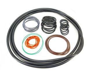
Thermal insulation plays a crucial role in maintaining temperature control and optimizing the efficiency of thermal injection molds. Insulating the mold helps to reduce heat loss, improve the stability of the molding process, and enhance overall productivity. In this section, we will discuss the process and considerations involved in adding thermal insulation to the mold.
Process Overview
- Evaluation: Evaluate the mold design and identify areas that may benefit from thermal insulation. Focus on areas where heat loss is likely to occur, such as the mold base, cavity walls, and cooling channels. Consider the material properties, process requirements, and desired temperature control when determining insulation needs.
- Insulation Selection: Select suitable insulation materials based on the specific requirements of the thermal injection mold. Common insulation materials include ceramic fiber, high-temperature foams, and specialized insulating coatings. Consider factors such as temperature resistance, thermal conductivity, and ease of application when choosing insulation materials.
- Application: Apply the chosen insulation materials to the mold surfaces requiring insulation. Follow the manufacturer's instructions for proper application techniques. Depending on the material, insulation can be applied through spraying, brushing, or adhering pre-cut insulation sheets. Ensure uniform coverage and a consistent thickness to achieve optimal insulation performance.
- Sealing: Seal the insulation material to prevent moisture absorption, protect against wear, and maintain insulation integrity. Use suitable sealants or coatings to create a barrier between the insulation and the mold surface. Ensure that the sealant is compatible with the insulation material and can withstand the operating temperatures of the thermal injection mold.
- Quality Control: Regularly inspect the insulation for any signs of damage or deterioration. Monitor the insulation thickness and integrity to ensure consistent performance. Replace or repair any damaged insulation promptly to maintain optimal thermal insulation properties.
Considerations
- Material Compatibility: Choose insulation materials that are compatible with the mold material and operating temperatures. Ensure that the insulation material can withstand the thermal cycling and mechanical stresses associated with the injection molding process. Consult material suppliers or experts if necessary to select the most suitable insulation materials.
- Thermal Conductivity: Consider the desired level of thermal conductivity when selecting insulation materials. Lower thermal conductivity values indicate better insulation performance, as they reduce heat transfer between the mold and the environment. Choose insulation materials with low thermal conductivity to maximize thermal insulation efficiency.
- Thickness: Determine the appropriate insulation thickness based on the temperature control requirements and the desired reduction in heat loss. Thicker insulation generally provides better thermal insulation, but it may also impact mold size, cooling efficiency, and cycle times. Strike a balance between insulation thickness and overall mold performance.
- Accessibility: Consider the accessibility of the mold surfaces when choosing insulation materials and application techniques. Ensure that the insulation can be applied to all relevant areas without hindering mold assembly, maintenance, or repair processes. Plan the insulation application to minimize interference with other mold components or features.
- Insulation Maintenance: Establish a regular maintenance schedule to monitor and maintain the insulation's performance. Inspect the insulation for signs of wear, damage, or degradation, such as cracks, peeling, or discoloration. Clean the insulation surfaces as needed to remove any contaminants that may affect its thermal properties.
Adding thermal insulation to a thermal injection mold is a crucial step in optimizing temperature control and improving molding efficiency. Evaluate the mold design, select suitable insulation materials, apply the insulation with proper techniques, and ensure effective sealing. Consider material compatibility, thermal conductivity, insulation thickness, accessibility, and maintenance when making insulation-related decisions. By following these considerations and best practices, you can enhance the thermal performance of the mold, leading to improved process stability and higher-quality molded parts.
Integrating Heating Elements
Introduction
Integrating heating elements into a thermal injection mold is essential for achieving precise temperature control during the injection molding process. Heating elements help maintain the mold at the desired temperature, ensuring consistent part formation and reducing the risk of defects. In this section, we will discuss the process and considerations involved in integrating heating elements into the mold.
Process Overview
- Evaluation: Evaluate the mold design and identify the areas where heating elements are required. Consider the part geometry, material properties, and process requirements to determine the appropriate locations for heating elements. Focus on areas that require precise temperature control, such as the mold cavity, core, or hot runner system.
- Heating Element Selection: Select the suitable heating elements based on the specific requirements of the thermal injection mold. Common heating elements include cartridge heaters, coil heaters, and flexible heating elements. Consider factorssuch as temperature range, heating capacity, size, and compatibility with the mold material when choosing heating elements.
- Integration: Integrate the selected heating elements into the mold design. This can be done by incorporating channels, grooves, or pockets in the mold where the heating elements will be placed. Work closely with mold designers or heating element suppliers to ensure proper placement and integration of the heating elements.
- Electrical Connections: Connect the heating elements to the power supply using appropriate wiring and connectors. Ensure that the electrical connections are secure, properly insulated, and comply with safety standards. It is recommended to consult with electrical experts or follow relevant electrical codes and regulations when making electrical connections.
- Temperature Control System: Install a temperature control system to regulate the heat output of the heating elements. This can be achieved using a thermocouple or a temperature sensor that measures the mold temperature and sends feedback to the controller. The controller adjusts the power supplied to the heating elements to maintain the desired temperature setpoint.
- Testing and Calibration: Perform thorough testing and calibration of the heating elements and temperature control system. Verify that the heating elements reach the desired temperature accurately and maintain temperature stability during the molding process. Make any necessary adjustments or fine-tuning to ensure optimal temperature control.
Considerations
- Temperature Range: Choose heating elements that can achieve and sustain the required temperature range for the specific injection molding process. Consider the material's melting point, processing temperature, and any temperature limitations of the mold material. Ensure that the heating elements can provide sufficient heat output to reach and maintain the desired temperatures.
- Heating Capacity: Consider the heating capacity required to heat the mold within the desired time frame. The heating elements should be able to provide enough heat to compensate for heat loss during the molding process, including heat absorbed by the injected material and cooling effects from the cooling system. Calculate the required heating capacity based on the mold size, material properties, and process parameters.
- Uniform Heating: Ensure that the heating elements provide uniform heat distribution throughout the mold. Uneven heating can lead to inconsistent part quality and dimensional variations. Consider the mold geometry and the placement of the heating elements to achieve uniform heat distribution. Use thermal analysis or conduct temperature measurements to verify the effectiveness of the heating element placement.
- Maintenance and Safety: Establish a maintenance plan for the heating elements to ensure their longevity and reliable performance. Regularly inspect the heating elements for any signs of damage, wear, or malfunction. Follow proper maintenance procedures, such as cleaning and replacing worn-out elements. Adhere to safety guidelines when working with electrical components and ensure that all electrical connections comply with safety standards.
- Compatibility with Cooling System: Consider the integration of heating elements with the cooling system in the mold design. Ensure that the heating elements do not interfere with the cooling channels or affect the cooling efficiency. Optimize the mold design to balance the heating and cooling requirements, ensuring efficient temperature control throughout the molding cycle.
Testing & Adjusting Temperature
Introduction
Once the thermal insulation and heating elements have been integrated into the thermal injection mold, it is essential to conduct thorough testing and adjustment of the temperature control system. This process ensures that the mold can achieve and maintain the desired temperatures for consistent and high-quality part production. In this section, we will discuss the steps involved in testing and adjusting the temperature of the mold.
Process Overview
- Preparation: Ensure that the mold is properly assembled and connected to the temperature control system. Verify that all electrical connections are secure and that the temperature sensors are correctly placed within the mold. Double-check that the mold surfaces are clean and free from any contaminants that could affect temperature measurements.
- Temperature Setpoints: Set the desired temperature setpoints for different areas of the mold, such as the cavity, core, or hot runner system. Consult the material specifications and process requirements to determine the appropriate temperature ranges. Input these setpoints into the temperature control system.
- Initial Calibration: Run the temperature control system and monitor the mold temperature using the temperature sensors. Allow the mold to heat up and stabilize at the desired temperature setpoints. During this calibration phase, observe the temperature readings and assess if they align with the setpoints. If there are significant deviations, adjustments may be necessary.
- Tuning: If there are temperature deviations, fine-tune the temperature control system to achieve accurate and stable temperatures. Adjust the power output to the heating elements based on the temperature readings. Gradually increase or decrease the power output and monitor the temperature response until the desired setpoints are consistently reached and maintained.
- Uniformity Check: Verify the temperature uniformity throughout the mold by measuring temperatures at multiple locations. Use thermocouples or temperature sensors placed strategically in different areas of the mold to ensure consistent heating. If significant temperature variations are detected, identify potential causes, such as insufficient heating elements or poor insulation, and make the necessary adjustments to achieve uniform heating.
- Testing Scenarios: Perform various testing scenarios to assess the mold's temperature control capabilities. Test the mold's ability to reach and maintain different temperature setpoints, including high and low ranges. Observe the mold's response to temperature changes, such as rapid heating or cooling, and confirm that the temperature control system can handle these transitions effectively.
- Data Logging: Implement a data logging system to record temperature readings during the testing phase. This data can be used for analysis and future reference, helping to identify any patterns or trends in temperature control. It also assists in troubleshooting and optimizing the temperature control system based on real-time data.
- Iteration and Optimization: Analyze the collected data and make any necessary adjustments to further optimize the temperature control system. Fine-tune the temperature setpoints, power output, or insulation if required. Repeat the testing and adjustment process until satisfactory temperature control is achieved consistently.
Considerations
- Material Requirements: Consider the specific requirements of the material being used in the injection molding process. Different materials have different optimal processing temperatures. Ensure that the mold can achieve and maintain the required temperature range for the material to ensure proper flow, curing, and part quality.
- Process Stability: Aim for stable and consistent temperatures throughout the molding process. Temperature deviations can lead to part defects, dimensional variations, or material inconsistencies. Strive for minimal temperature fluctuations by optimizing the temperature control system and insulation.
- Thermocouple Placement: Carefully position the thermocouples or temperature sensors within the mold to accurately measure temperatures. Place them at critical locations that reflect the actual temperature conditions experienced by the molded parts. Ensure that the thermocouples are securely attached and in direct contact with the mold surfaces for accurate readings.
- Real-Time Monitoring: Implement a real-time monitoring system to continuously observe the mold temperature during production. This allows for immediate detection of any temperature deviations or irregularities, enabling prompt corrective actions to maintain consistent part quality.
- Safety: Follow proper safety protocols when working with the temperature control system and electrical components. Ensure that the system is correctly grounded, and all electrical connections comply with safety standards. Regularly inspect the system for any signs of wear or damage that could pose a safety risk.
Testing and adjusting the temperature control system of a thermal injection mold is crucial to ensure accurate and stable temperature control during the molding process. Proper preparation, calibration, tuning, and uniformity checks are essential steps in achieving consistent and high-quality part production. Consider material requirements, process stability, thermocouple placement, real-time monitoring, and safety when conducting temperature testing and adjustments. By following these considerations and best practices, you can optimize the temperature
Molding Demo & First Sample Part
Introduction
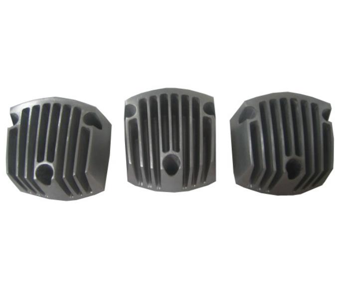
Once the temperature control system has been tested and adjusted, the next step in the thermal injection molding process is to perform a molding demonstration and produce the first sample part. This stage allows for the validation of the mold design, process parameters, and overall functionality of the thermal injection molding system. In this section, we will discuss the key aspects involved in the molding demo and the production of the first sample part.
Process Overview
- Mold Preparation: Ensure that the thermal injection mold is properly cleaned and free from any debris or contaminants. Verify that the mold surfaces are adequately lubricated to facilitate part ejection. Double-check the alignment of the mold halves and confirm that all moving components, such as slides or lifters, are functioning correctly.
- Material Selection: Choose the appropriate material for the sample part based on the desired properties, application requirements, and compatibility with the thermal injection molding process. Consider factors such as melt temperature, viscosity, and shrinkage characteristics. Consult material data sheets and processing guidelines to determine the optimal processing parameters.
- Material Preparation: Prepare the selected material for the molding process. This may involve drying the material if necessary, as some thermoplastics are sensitive to moisture. Follow the material manufacturer's recommendations for drying time and temperature to ensure proper material handling.
- Injection Molding Machine Setup: Set up the injection molding machine according to the mold and material specifications. Install the mold securely in the machine, ensuring proper alignment and connection to the temperature control system. Configure the machine parameters, such as injection pressure, injection speed, and melt temperature, based on the material requirements.
- Purge and Preheating: Purge the injection molding machine with a small amount of material to remove any residual material or contaminants from the previous run. Once the machine is purged, preheat the mold to the desired temperature setpoints. This preheating step ensures that the mold is at the optimal temperature for the initial shot of material.
- Molding Demonstration: Initiate the molding process by injecting the material into the heated mold cavity. Observe the filling behavior, flow patterns, and venting of the mold. Assess the overall performance of the mold and the injection molding machine, including part ejection, cycle time, and any potential issues or defects that may arise.
- Sample Part Inspection: After the molding demonstration, remove the sample part from the mold and inspect it for quality and adherence to design specifications. Evaluate the part's dimensional accuracy, surface finish, and any visible defects. Compare the sample part with the intended design to ensure alignment.
- Process Optimization: Analyze the results of the molding demonstration and sample part inspection. Identify any areas for improvement or optimization in the mold design, process parameters, or material selection. Make adjustments as necessary to enhance part quality, reduce cycle time, or address any defects or issues encountered during the molding process.
- Documentation and Reporting: Document the results of the molding demonstration and sample part inspection. Record any observations, measurements, or data collected during the process. This documentation provides a reference for future production runs and serves as a basis for continuous improvement in the thermal injection molding process.