Introduction
You’ve designed a part. It looks perfect on screen. But when the first parts come off the production line, something’s off. The holes don’t align. The snap fits don’t click. The assembly won’t close.
This is the reality of tolerances for injection molded parts. Every manufacturing process has variation. The key is understanding what variation is acceptable—and how to control it.
Tolerances define the acceptable range of deviation from your design dimensions. Get them too tight, and you’ll pay a fortune for precision that isn’t needed. Get them too loose, and your product won’t function or assemble correctly.
This guide walks you through everything that affects tolerances: material behavior, mold design, processing conditions, and measurement methods. You’ll learn how to set realistic tolerances and work with manufacturers to achieve them consistently.
Why Do Tolerances Actually Matter?
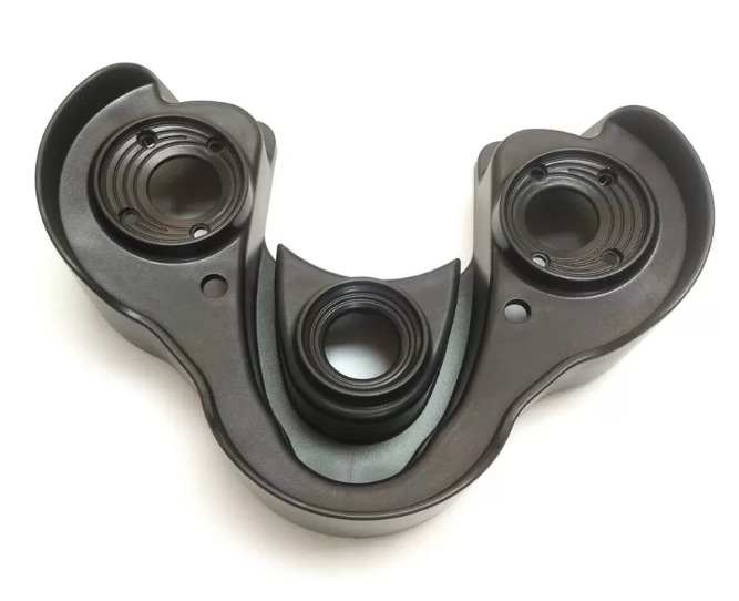
Functionality Depends on Fit
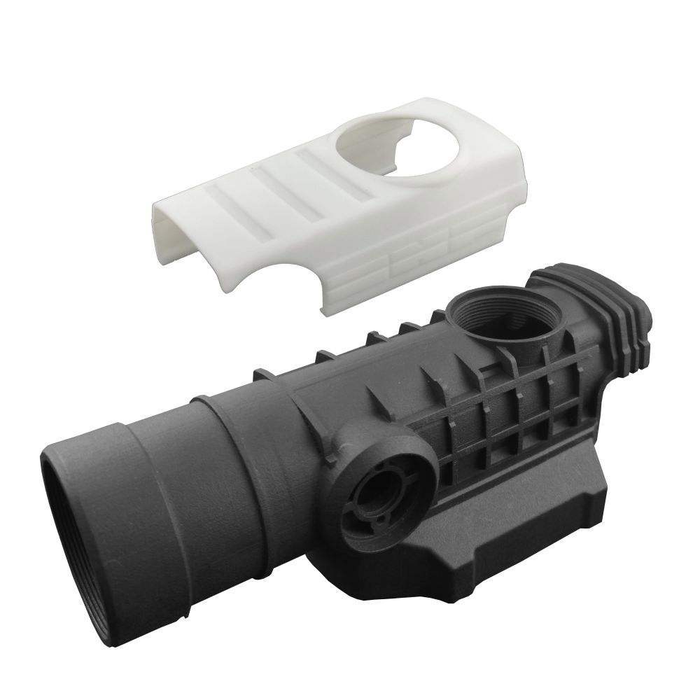
Parts that don’t fit together correctly are useless. In an automotive engine, a plastic cover with poor tolerances might leak oil. In a medical device, a misaligned component could cause failure at a critical moment.
A study by the Society of Plastics Engineers found that over 30% of product failures in the automotive industry trace back to improper tolerancing of plastic parts. That’s not a small number. It represents recalls, warranty claims, and damaged reputations.
Assembly Drives Production Cost
When parts don’t fit, assembly slows down. Workers struggle to snap components together. Production lines stop. Rework piles up.
Consider a consumer electronics assembly line. If housing tolerances are off by just 0.2 mm, it might take twice as long to close each device. Over 100,000 units, that extra time costs thousands in labor—and delays shipments.
Quality Defines Your Brand
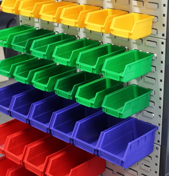
Tight tolerances signal high-quality manufacturing. Loose tolerances signal the opposite. Customers may not know the term “tolerance,” but they notice when a product feels cheap or doesn’t fit right.
In the medical device industry, the stakes are even higher. A deviation that seems tiny can have life-threatening consequences. That’s why medical manufacturers typically require tolerances of ±0.01 mm to ±0.05 mm on critical features.
What Factors Influence Tolerances?
Material Choice Is Fundamental
Different plastics shrink at different rates. Shrinkage is the reduction in size as the part cools from melt temperature to room temperature. If you don’t account for it, your parts will be smaller than your mold.
| Material | Typical Shrinkage Rate | Tolerance Impact |
|---|---|---|
| PP (Polypropylene) | 1.5% – 3.5% | High variation |
| ABS | 0.4% – 0.9% | Moderate, stable |
| PC (Polycarbonate) | 0.5% – 0.7% | Low, consistent |
| POM (Acetal) | 1.5% – 2.5% | Moderate |
A manufacturer running a 10,000-part production run in PP will see more dimensional variation than the same run in ABS. For tight-tolerance applications, materials with low and consistent shrinkage—like PC or ABS—are often preferred.
Real example: A medical device company originally specified PP for a precision component. Parts varied so much that 15% failed inspection. Switching to PC reduced the reject rate to under 2%. The material cost was higher, but total cost dropped due to fewer rejects.
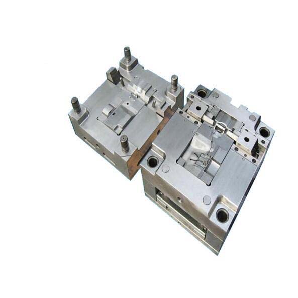
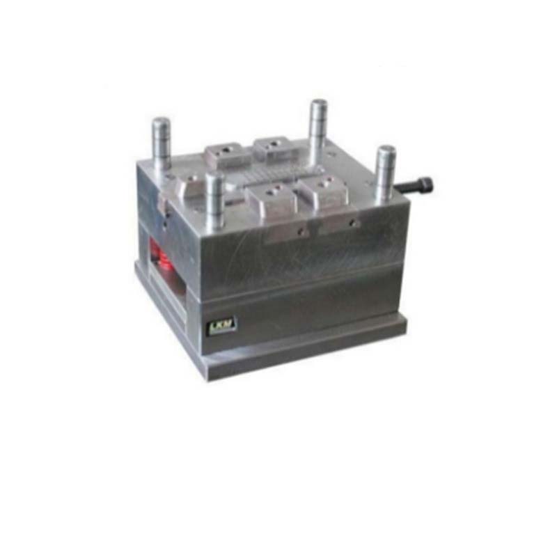
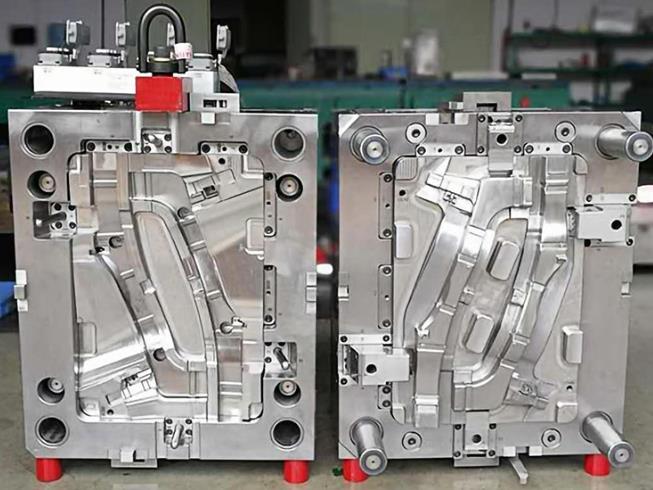
Mold Design Determines Consistency
The mold itself is a major source of variation—or consistency.
Mold structure: If mold plates are misaligned, wall thickness varies. A study in the Mold Making Technology Journal found that misaligned plates caused up to 20% of parts to exceed tolerance limits.
Gate location: The gate is where molten plastic enters the cavity. Place it wrong, and filling becomes uneven. A study of 500 parts with improper gate locations found that over 30% had significant warping issues.
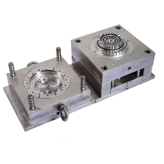
Cooling channels: Uneven cooling creates internal stresses. Those stresses cause warpage. A well-designed cooling system keeps temperatures uniform across the part.
A consumer goods company struggled with warped lids on food containers. The issue traced back to a single cooling channel placed too far from a critical feature. Adding a channel cut warpage by 70%.
Processing Conditions Drive Daily Variation
Even with the right material and mold, daily processing conditions affect tolerances.
Temperature effects:
- Higher melt temperature increases shrinkage
- For every 10°C above recommended range, shrinkage increases by roughly 0.1%
- Uneven mold temperature creates differential cooling and warpage
Pressure effects:
- Injection pressure must be high enough to fill the cavity but not so high it causes flash
- Holding pressure compensates for shrinkage as the part cools
- A 10% increase in holding pressure can reduce shrinkage by 0.05–0.1 mm, depending on material
Time effects:
- Cooling time must be sufficient for full solidification
- Reducing cooling time by 20% can increase final dimensions by 0.2–0.3 mm
A packaging manufacturer reduced cooling time to boost output. Parts grew beyond tolerance. They restored cooling time and added a second cavity instead—maintaining tolerances while still increasing production.
What Tolerance Standards Should You Use?
ISO Standards
ISO 294-4 is the international standard for injection-molded thermoplastic part tolerances. It classifies tolerances into grades based on part size.
| Nominal Dimension | Tolerance Grade MT2 | Tolerance Grade MT3 |
|---|---|---|
| Up to 3 mm | ±0.05 mm | ±0.10 mm |
| 3–6 mm | ±0.07 mm | ±0.12 mm |
| 6–10 mm | ±0.08 mm | ±0.15 mm |
| 10–18 mm | ±0.10 mm | ±0.18 mm |
| 18–30 mm | ±0.12 mm | ±0.20 mm |
| 30–50 mm | ±0.15 mm | ±0.25 mm |
| 50–80 mm | ±0.20 mm | ±0.30 mm |
MT2 is for precision parts. MT3 covers general-purpose applications. MT4 and above are for loose tolerances.
ASTM Standards
ASTM provides complementary standards:
- ASTM D4000: System for specifying plastic materials
- ASTM E228: Method for measuring thermal expansion
These help predict how materials behave during molding and cooling.
Comparing Standards
For a 50 mm nominal dimension:
| Standard | Tolerance Grade | Range |
|---|---|---|
| ISO 294-4 MT3 | Medium precision | ±0.25 mm |
| DIN 16749 | Finer class | ±0.12 mm |
| ASTM (equivalent) | Medium precision | ±0.1–0.2 mm |
Different industries prefer different standards. Medical typically follows ISO. Automotive often uses IATF requirements built on ISO. Consumer goods may use internal standards based on function and cost.
How Do You Measure and Control Tolerances?
Measurement Tools for Every Situation
| Tool | Best For | Typical Accuracy |
|---|---|---|
| Calipers | Linear dimensions, simple parts | ±0.01 mm |
| Micrometers | Small features, hole diameters | ±0.001 mm |
| CMM (Coordinate Measuring Machine) | Complex geometries, 3D shapes | ±0.002–0.005 mm |
| Optical comparators | Profile checking, fast inspection | ±0.005 mm |
| Laser scanners | Large parts, full-surface measurement | ±0.01–0.05 mm |
A CMM is essential for complex parts. One automotive supplier uses CMM to inspect every critical dimension on engine components. The upfront investment in equipment pays back through zero tolerance-related field failures.
Quality Control Through Production
First-article inspection (FAI):
The first parts from a new mold or setup undergo full dimensional inspection. FAI catches issues before mass production begins. Studies show FAI can reduce mass-production defect rates by up to 50%.
In-process inspection:
Parts are checked at regular intervals—every 100 parts, every hour, or at set times. This catches process drift early. One large injection molding facility reported a 30% reduction in out-of-tolerance parts after implementing hourly in-process checks.
Final inspection:
Before shipping, parts receive a final check. Critical dimensions are verified. Visual defects are caught. This last step prevents defective parts from reaching customers.
A medical device manufacturer uses all three levels. First-article catches tooling issues. In-process catches process shifts. Final inspection provides documented traceability. Their field defect rate is below 0.1%.
How Do You Set Realistic Tolerances?
Start with Function
The tightest tolerance you can achieve isn’t always the right one. Start by asking: what does this dimension actually need to do?
- Critical features: Assembly points, sealing surfaces, mating dimensions—tight tolerances
- Non-critical features: Cosmetic surfaces, free-standing geometry—looser tolerances
A consumer electronics company once specified ±0.05 mm on every dimension of a device housing. The mold cost $95,000. After reviewing actual assembly needs, they relaxed non-critical dimensions to ±0.15 mm. The second mold cost $52,000 and worked just as well.
Understand Process Capability
Every process has natural variation. A good manufacturer knows what’s achievable for your part geometry and material.
Ask your manufacturer:
- What tolerances can you consistently hold for this design?
- What drives variation in similar parts you’ve made?
- Where should I be tighter or looser?
Add Tolerances to the Part, Not Just the Drawing
Tolerances on a drawing are meaningless if they aren’t achievable. Work with your manufacturer during design to ensure:
- Tolerances align with material capabilities
- Critical dimensions are measurable
- Tolerances aren’t tighter than needed
Conclusion
Setting and controlling tolerances for injection molded parts requires balancing function, cost, and manufacturability. Material choice sets the foundation. Mold design and processing conditions determine consistency. Measurement and quality control verify results.
The goal isn’t the tightest tolerance possible. It’s the right tolerance for your application—achieved consistently, cost-effectively, and verified through robust quality processes.
Work closely with your manufacturer during design. Understand what drives variation. And remember: a part that meets its tolerances every time is worth more than a part that only sometimes meets tighter ones.
FAQ
What is the typical tolerance range for injection molded parts?
Typical ranges vary widely. Consumer parts often use ±0.2–0.5 mm. Precision parts can achieve ±0.01–0.05 mm. Material matters—low-shrinkage materials like PC and ABS hold tighter tolerances than PP or PE. Part size also affects achievable tolerances; larger parts have proportionally larger variations.
How can I reduce tolerances in injection molding?
Start with low-shrinkage, stable materials. Use high-precision molds with proper cooling and gate design. Control processing conditions tightly—temperature, pressure, and cycle times. Implement first-article, in-process, and final inspection. Work with a manufacturer experienced in your industry’s tolerance requirements.
Do tight tolerances increase part cost?
Yes, significantly. Tighter tolerances require more precise molds, which cost more to build. Processing requires tighter controls, which may mean slower cycles and more inspections. Tightening a tolerance from ±0.2 mm to ±0.05 mm can increase part cost by 30–50% . Always ask: does this dimension really need that tolerance?
What’s the difference between ISO and ASTM tolerance standards?
ISO 294-4 provides specific tolerance grades for injection-molded thermoplastic parts. ASTM provides broader material specifications and test methods. Many manufacturers reference both—ISO for dimensional tolerances, ASTM for material properties. Medical and automotive industries often specify ISO standards.
How do I verify my manufacturer is holding tolerances?
Request first-article inspection reports with CMM data. Ask for in-process inspection records. Require material certifications. If possible, visit the facility to see quality processes firsthand. A manufacturer confident in their capabilities will share this documentation without hesitation.
Contact Yigu Technology for Custom Manufacturing
At Yigu Technology, we understand that tight tolerances aren’t just numbers on a drawing—they’re the difference between a product that works and one that doesn’t. Our engineers work with you from the start, selecting materials and designing molds to achieve consistent, repeatable results.
We combine:
- Advanced simulation tools to predict and optimize tolerances
- High-precision CNC and EDM equipment
- Rigorous quality control at every stage
- Transparent communication throughout your project
[Contact Yigu Technology today] to discuss your tolerance requirements. Let’s build parts that fit right the first time, every time.