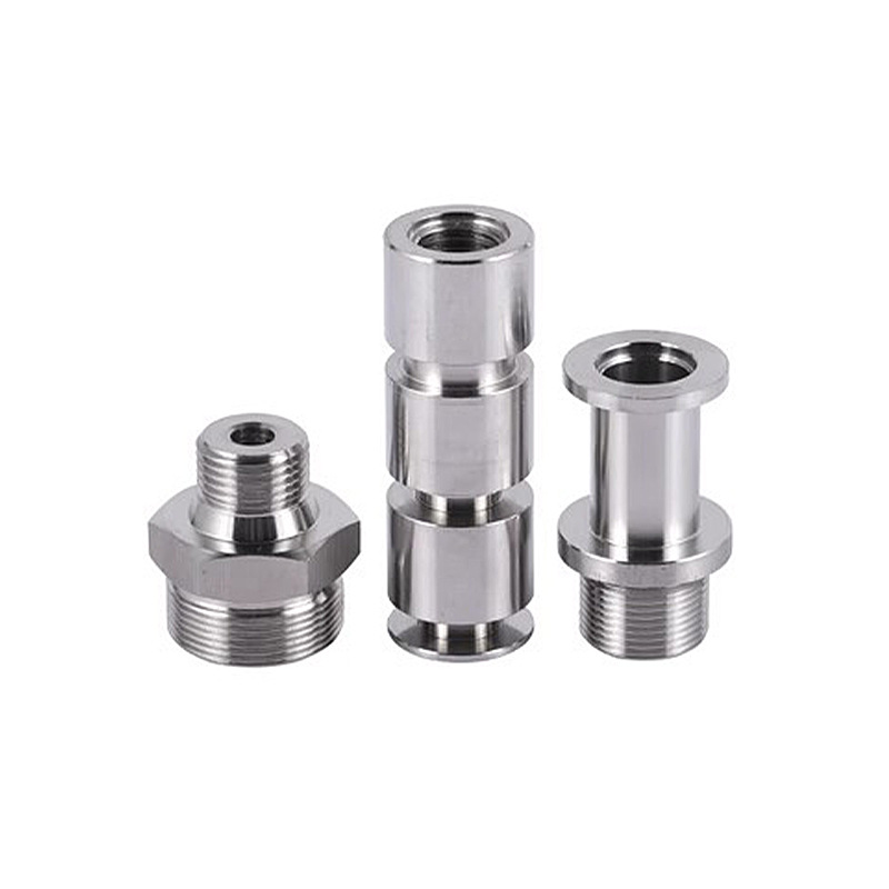
1 Understanding CNC Machining Technology
1.1 Definition and Concept
CNC, short for Computer Numerical Control, represents a revolutionary technology in the manufacturing industry. It involves the use of computer - controlled machines to execute a wide range of manufacturing tasks with a high degree of precision and repeatability. In essence, CNC technology replaces the manual operation of machine tools with pre - programmed instructions stored in a computer.
In contrast, CNC machining offers several distinct advantages. It can produce parts with a high level of accuracy, often within micrometers. For instance, in the aerospace industry, where components such as turbine blades require extremely tight tolerances, Yigu Technology CNC machining can meet these strict requirements consistently. Moreover, CNC machines can work continuously for long periods without fatigue, significantly increasing productivity. They can also handle complex geometries that are nearly impossible to achieve through manual machining. For example, a 5 - axis CNC machine can simultaneously control the movement of the workpiece and the cutting tool in five different directions, enabling the creation of intricate shapes such as the complex impellers used in high - performance engines.
1.2 The Working Principle of CNC Machines
The working principle of CNC machines can be divided into several key steps.
Instruction Input: The process begins with the creation of a CNC program. This program is typically developed using Computer - Aided Manufacturing (CAM) software. The programmer uses the CAM software to import a 3D model of the part to be machined, which is usually created in a Computer - Aided Design (CAD) program. The CAM software then analyzes the part's geometry and generates a set of instructions that describe how the machine should move the cutting tool to shape the workpiece. These instructions are in the form of G - code, a standardized programming language for CNC machines. For example, a simple G - code instruction like "G01 X10 Y20 F100" tells the machine to move the cutting tool in a straight line to the coordinates X = 10 and Y = 20 at a feed rate of 100 millimeters per minute.
Numerical control system processing: Once the G - code program is created, it is transferred to the CNC machine's control unit. The control unit, which is essentially a specialized computer, reads and interprets the G - code instructions. It decodes each line of the G - code, extracting information such as the target coordinates, feed rate, spindle speed, and tool selection. The control unit then calculates the precise movements required for each axis of the machine to execute the instructions.
Servo Drive Execution: The control unit sends signals to the servo drives, which are responsible for powering and controlling the motors that move the machine's axes. Servo drives are like the "muscles" of the CNC machine. For example, in a three - axis CNC mill, there will be servo drives for the X, Y, and Z axes. Each servo drive receives the control signals from the control unit and adjusts the speed and position of its corresponding motor accordingly. The motors, in turn, drive the ball screws or linear guides that move the machine's table, spindle, and other components. High - precision encoders are often attached to the motors or the axes themselves. These encoders continuously send feedback signals to the servo drives, indicating the actual position and speed of the axes. The servo drives compare the feedback signals with the desired values sent by the control unit. If there is any deviation, the servo drives adjust the motor's operation to correct the error, ensuring that the axes move precisely as commanded.
| Component | Function | Example |
| Instruction Input | Creation of CNC program using CAM software and transfer to control unit | Importing a CAD model into CAM software like Mastercam to generate G - code |
| 数控系统处理 | Decoding and calculation of G - code instructions | Control unit interpreting "G01 X10 Y20 F100" and calculating axis movements |
| Servo Drive Execution | Powering motors and adjusting based on feedback | Servo drives controlling X, Y, Z axis motors in a CNC mill with encoder feedback |
2. CNC Programming Basics
2.1 Programming Languages in CNC (G - code and M - code)
In Yigu Technology CNC machining, G - code and M - code are the two fundamental programming languages that enable the control of machine tools.
G - code is primarily responsible for controlling the movement paths of the machine's axes. It defines how the cutting tool moves relative to the workpiece, determining the shape and dimensions of the final product. For example, G00 is a commonly used G - code for rapid positioning. When the machine reads "G00 X50 Y30", it quickly moves the cutting tool to the coordinates X = 50 and Y = 30 without cutting material. This is useful for quickly positioning the tool at the starting point of a machining operation or moving it between different machining positions. Another important G - code is G01, which represents linear interpolation. An instruction like "G01 X20 Y10 Z5 F150" tells the machine to move the tool in a straight - line to the point (X = 20, Y = 10, Z = 5) at a feed rate of 150 millimeters per minute while cutting material. This is used for basic straight - line cutting operations. G02 and G03 are for circular interpolation, with G02 for clockwise circular movement and G03 for counter - clockwise. For instance, in the production of a circular - shaped part, a programmer might use G02 to create the outer contour of a circular groove.
M - code, on the other hand, controls the auxiliary functions of the CNC machine. M03 is used to start the spindle in the clockwise direction. In a milling operation, this is essential as it rotates the cutting tool, allowing it to remove material from the workpiece. M04 starts the spindle in the counter - clockwise direction, which might be required for certain operations or tool changes. M05 stops the spindle, typically at the end of a machining operation or when changing tools. M06 is the code for automatic tool change. In a multi - step machining process where different cutting tools are needed, this code enables the machine to switch tools accurately and efficiently. For example, in the production of a complex mechanical part that requires drilling, milling, and tapping operations, the machine will use M06 to change from a drill bit to a milling cutter and then to a tap at the appropriate times. M08 and M09 are for turning on and off the coolant respectively. Coolant is crucial in CNC machining as it helps to reduce heat generated during cutting, prolong the life of the cutting tool, and improve the surface finish of the workpiece.
| Code Type | Code | Function | Example of Use |
| G - code | G00 | Rapid positioning | Move the tool quickly to the starting point of a machining area: G00 X100 Y50 |
| G - code | G01 | Linear interpolation | Cut a straight - line segment: G01 X30 Y40 Z10 F100 |
| G - code | G02 | Clockwise circular interpolation | Create a circular arc in the clockwise direction for a circular feature |
| G - code | G03 | Counter - clockwise circular interpolation | Create a circular arc in the counter - clockwise direction for a circular feature |
| M - code | M03 | Start spindle clockwise | Begin a milling operation by rotating the cutting tool clockwise |
| M - code | M04 | Start spindle counter - clockwise | |
| M - code | M05 | Stop spindle | End a machining operation and stop the tool rotation |
| M - code | M06 | Automatic tool change | Switch from a drill bit to a milling cutter during a multi - step machining process |
| M - code | M08 | Turn on coolant | Cool the cutting area during machining to prevent overheating |
| M - code | M09 | Turn off coolant | Stop coolant flow at the end of a machining step |
2.2 The Role of CAM Software in Programming
CAM (Computer - Aided Manufacturing) software plays a pivotal role in CNC programming. Its primary function is to transform the design data from a CAD (Computer - Aided Design) model into machine - readable instructions that can be executed by a CNC machine.
When a Yigu Technology designer creates a 3D model of a part using CAD software, such as SolidWorks or AutoCAD, the model contains all the geometric information about the part, including its shape, dimensions, and surface features. CAM software imports this CAD model and then analyzes it to generate the necessary tool paths. It takes into account various factors like the type of machining operation (milling, turning, drilling, etc.), the material of the workpiece, and the capabilities of the CNC machine. For example, if the part has complex curved surfaces, the CAM software will calculate the optimal tool paths to ensure that the cutting tool can accurately shape these surfaces while maintaining the required tolerance.
2.3 Programming Process
2.3.1 Analyzing the Part Design
Analyzing the part design is the initial and crucial step in creating a CNC program. When presented with a part design, whether it's in the form of a 2D drawing or a 3D CAD model, the programmer must first identify the key dimensions. These are the dimensions that are critical to the functionality and fit of the part. For example, in a precision - engineered engine component, the dimensions of the piston bore must be extremely accurate to ensure proper engine performance. Any deviation from the specified tolerance in this dimension could lead to engine inefficiencies or even failure.
The shape of the part also needs to be carefully examined. Complex shapes, such as those with curved surfaces or irregular profiles, require special consideration in terms of the machining operations and tool paths. For instance, a part with a free - form surface, like a turbine blade, will need a more intricate machining strategy compared to a simple rectangular block. The programmer must determine the best way to machine these shapes using the available CNC machine and cutting tools.
2.3.2 Creating the Tool Path
Creating the tool path is a central part of CNC programming. The tool path determines the sequence and trajectory of the cutting tool's movement during the machining process. When creating the tool path, the programmer must consider the cutting sequence. This involves deciding which areas of the workpiece to machine first and in what order. For example, in a multi - step milling operation, it is often advisable to rough - machine the part first to remove the majority of the excess material quickly. This is usually followed by a finishing operation to achieve the final dimensions and surface finish. Rough - machining can be done with a larger cutting tool and higher feed rates to save time, while finishing requires a smaller, more precise tool and lower feed rates to ensure accuracy.
The feed rate is another crucial factor. It refers to the speed at which the cutting tool advances along the tool path. A proper feed rate is essential to ensure efficient material removal and good surface finish. If the feed rate is too high, it can cause the cutting tool to overheat, wear out quickly, and may even result in a poor surface finish or dimensional inaccuracies. On the other hand, if the feed rate is too low, the machining process will be time - consuming and uneconomical. For example, when machining a soft material like plastic, a relatively high feed rate can be used, perhaps around 200 - 500 millimeters per minute, depending on the type of plastic and the cutting tool. But when machining a hard metal like steel, the feed rate may need to be reduced to 50 - 150 millimeters per minute.
2.3.3 Code Generation and Simulation
After creating the tool path, the next step is code generation. The tool path information is translated into G - code, which is the language that the CNC machine can execute. CAM software usually takes care of this conversion automatically. It generates a series of G - code instructions based on the tool path, spindle speed, feed rate, and other machining parameters. For example, if the tool path consists of a linear movement from point A to point B at a certain feed rate and spindle speed, the CAM software will generate the corresponding G - code instructions such as "G01 X[coordinate of point B] Y[coordinate of point B] F[feed rate] S[spindle speed]".
Before running the G - code program on the actual CNC machine, it is essential to use simulation tools. Simulation allows the programmer to visualize the machining process on a computer screen. The simulation software takes the G - code and animates the movement of the cutting tool and the workpiece. This helps in detecting potential issues such as collisions between the cutting tool and the workpiece or other parts of the machine, incorrect tool paths that may lead to over - cutting or under - cutting, and improper machining sequences.
3 Key Elements in CNC Machining and Programming
3.1 Accuracy and Precision
Accuracy and precision are of utmost importance in Yigu Technology CNC machining. In CNC machining, accuracy refers to how close the actual dimensions of the machined part are to the designed dimensions, while precision relates to the consistency and repeatability of the machining process. For example, in the production of aerospace components, a turbine blade might have a design specification for a particular airfoil shape with tolerances in the range of ±0.05 mm. Achieving this level of accuracy is crucial as even a small deviation can significantly affect the aerodynamic performance and efficiency of the engine. In the medical industry, components such as orthopedic implants also demand high precision. A hip implant, for instance, needs to fit precisely into the patient's anatomy. If the dimensions are off by even a fraction of a millimeter, it can lead to discomfort, implant failure, or the need for additional surgeries.
3.2 Tool Selection and Management
Selecting the right cutting tools for a CNC machining operation is a critical decision that depends on various factors. The material of the workpiece is a primary consideration. Different materials have different hardness levels and machining characteristics. For example, when machining aluminum, high - speed steel (HSS) or carbide - coated tools can be used effectively. Aluminum is a relatively soft material, so HSS tools can cut through it at high speeds, and the carbide coating can further enhance the tool's durability. In contrast, when machining hardened steel, carbide or cubic boron nitride (CBN) tools are more suitable. Hardened steel is extremely tough, and carbide and CBN tools have the hardness and heat - resistance required to cut through it without excessive wear.
3.3 Workpiece Setup and Fixturing
Proper workpiece setup and fixturing are fundamental to achieving accurate and efficientYigu Technology CNC machining. When setting up the workpiece, ensuring its stability is crucial. A workpiece that is not firmly secured can move during the machining process, leading to significant errors. For example, in a milling operation, if the workpiece is not clamped tightly, it can shift slightly under the force of the cutting tool. This can result in inaccurate dimensions, a poor surface finish, and even damage to the tool and the workpiece.
4 Conclusion
In Yigu Technology conclusion, CNC machining and programming are fundamental aspects of modern manufacturing. The technology has revolutionized the production process, enabling the creation of high - precision parts with efficiency and consistency. Understanding the basics of CNC machining, from the working principle of CNC machines to the intricacies of programming languages like G - code and M - code, is essential for anyone involved in the manufacturing industry.
The role of CAM software in streamlining the programming process cannot be overstated. It not only reduces the time and effort required for programming but also minimizes the risk of errors. Key elements such as accuracy, precision, proper tool selection, and workpiece setup are crucial for achieving high - quality results in Yigu Technology CNC machining. Each of these elements is interdependent, and a small oversight in one area can have a significant impact on the overall outcome of the machining process.
As the manufacturing industry continues to evolve, with the increasing demand for complex and high - precision components in industries like aerospace, automotive, medical, and electronics, CNC machining and programming will play an even more critical role. New technologies and techniques are constantly emerging, such as multi - axis machining, 智能化编程,and the integration of CNC machines with the Internet of Things (IoT). These advancements offer exciting opportunities for manufacturers to further improve efficiency, quality, and productivity.
