Introduction
In modern manufacturing, CNC machined parts represent the pinnacle of precision and flexibility. Unlike additive processes like 3D printing, CNC machining is a subtractive technique where material is precisely removed from a solid block—the workpiece—using computer-controlled cutting tools. This digital control transforms raw materials into components with exceptional dimensional accuracy and surface finishes.
From medical implants that save lives to aerospace components that defy gravity, the reliability of these parts hinges on the sophisticated process behind them. This guide demystifies CNC machining—explaining how it works, why it is the preferred method for engineers and designers, and providing practical insights on materials, design, tolerances, and cost to inform your next project.
What Is a CNC Machined Part?
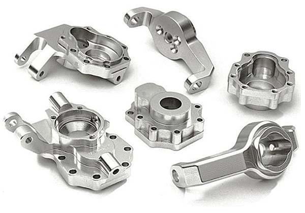
A CNC machined part is a component manufactured using Computer Numerical Control (CNC) technology. The process begins with a digital 3D model (CAD file), which is converted into numerical instructions called G-code. This code directs the precise movements of factory machinery and cutting tools to carve, drill, and shape the part from a solid material block.
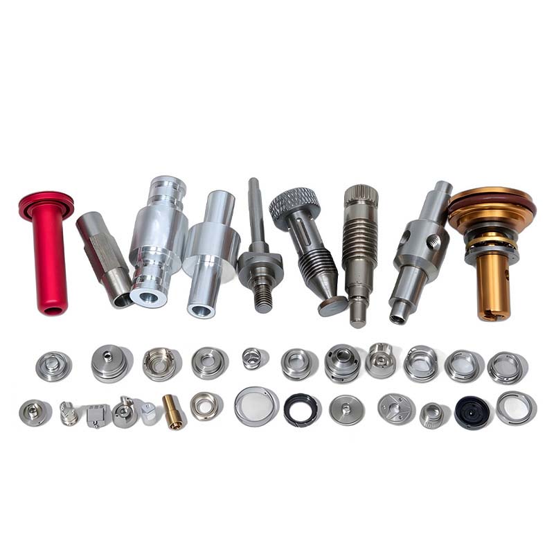
The defining characteristic of these parts is their high degree of accuracy and repeatability. Once a program is verified, a CNC machine can produce thousands of identical parts with minimal variation—ideal for both prototyping and mass production. Common examples range from simple brackets and gears to complex components like turbine blades and surgical instrument housings.
How Does CNC Machining Work?
The Core Workflow
| Step | Description |
|---|---|
| Design (CAD) | Create detailed 3D model using Computer-Aided Design (CAD) software |
| Programming (CAM) | Import CAD file into CAM software; define toolpaths, select cutting tools, set speed/feed rates; generate G-code |
| Setup | Secure workpiece (vise, clamp, fixture); load cutting tools into tool changer or spindle |
| Machining Execution | CNC controller executes G-code; drives servo motors moving tool and/or workpiece along multiple axes; removes material layer by layer |
| Finishing | Secondary operations—deburring, polishing, anodizing, plating—as required |
Primary CNC Processes
| Process | Description | Best For |
|---|---|---|
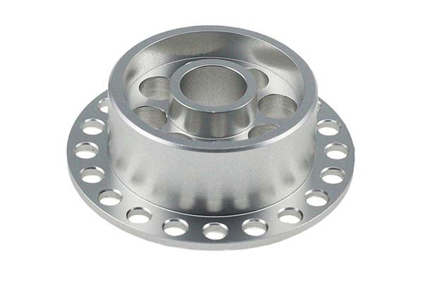
| CNC milling | Rotating cutting tool moves along multiple axes (X, Y, Z); stationary workpiece | Pockets, slots, complex 3D contours |
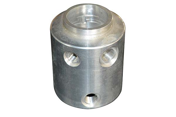
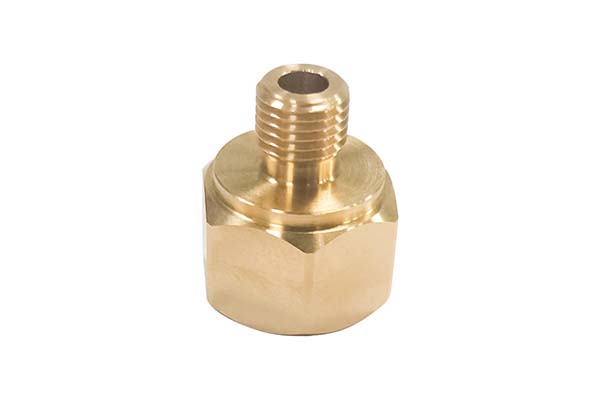
| CNC turning | Workpiece rotates at high speed; stationary cutting tool | Cylindrical/conical parts—shafts, bushings, rings |
| Multi-axis machining | 5-axis machines move tool or workpiece along five+ axes simultaneously | Extremely complex geometries—aerospace impellers, medical implants; single setup |
What Materials Are Used in CNC Machining?
| Material Category | Common Examples | Key Properties & Applications |
|---|---|---|
| Metals | Aluminum (6061, 7075) | Excellent strength-to-weight; good machinability; corrosion resistant—automotive, aerospace, consumer electronics |
| Stainless steel (304, 316) | High strength; superior corrosion resistance—medical devices, food processing, marine | |
| Titanium (Ti-6Al-4V) | Exceptional strength-to-weight; biocompatible—aerospace components, medical implants | |
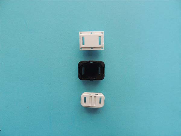
| Plastics | PEEK | High-performance thermoplastic; thermal stability; chemical resistance; strength—demanding automotive, aerospace, medical |
| Acetal (POM/Delrin) | High stiffness; low friction; dimensional stability—gears, bearings, precision insulators | |
| Nylon (PA) | Tough; wear-resistant; good mechanical properties—functional prototypes, durable parts | |
| Other | Wood, composites, graphite | Prototypes, molds, specialized fixtures, EDM electrodes |
What Are the Key Advantages of CNC Machined Parts?
| Advantage | Description |
|---|---|
| Superior precision and repeatability | Tolerances typically ±0.025 mm (±0.001″) for milling; often finer for turning—maintained across every part in production run |
| Complex geometrical freedom | Multi-axis capabilities enable shapes impossible or prohibitively expensive with manual machining or molding—internal features, undercuts, true 3D contours |
| Broad material compatibility | Processes virtually any rigid material—soft plastics, aluminum, superalloys (Inconel) |
| Efficiency and scalability | Initial setup/programming investment; automated tool changers; pallet systems enable lights-out (unmanned) manufacturing—reduces per-part cost at scale |
What Industries Rely on CNC Machined Parts?
| Industry | Applications | Requirements |
|---|---|---|
| Aerospace & Defense | Engine mounts, landing gear parts, UAV frames | Extreme reliability; lightweight design; stress resistance—titanium, high-grade aluminum |
| Medical & Dental | Surgical tools, orthopedic implants (knee joints), diagnostic equipment housings | Biocompatible materials (titanium, PEEK); absolute sterility; flawless surface finishes |
| Automotive & Motorsports | Prototyping new engine designs; transmission components; custom fittings | Rapid iteration; durable, heat-resistant materials |
| Electronics | Heat sinks for processors; connectors; enclosures | Precision for fit; thermal management; electromagnetic shielding |
How to Maintain Precision and Tolerances?
| Factor | Description |
|---|---|
| Machine calibration and rigidity | Regular calibration (laser interferometers); robust construction (polymer concrete bases)—minimizes vibration and thermal distortion |
| Tooling strategy | Premium sharp tools; high-precision tool holders (shrink-fit)—minimizes runout and deflection; proactive tool wear monitoring |
| Thermal management | Coolant; temperature-controlled environment—critical for materials with high thermal expansion (aluminum) |
| Fixturing | Immovable workpiece holding; custom fixtures; precision vises—essential for multi-operation machining |
What Quality Control Processes Ensure Reliability?
| Process | Description |
|---|---|
| First Article Inspection (FAI) | Comprehensive dimensional check of first part from new setup; verifies every feature against engineering drawing; report often required for customer approval |
| In-Process Inspection | On-machine probes check critical dimensions during production run; real-time adjustments compensate for tool wear |
| Final Inspection with Advanced Metrology | CMMs, optical comparators, surface roughness testers—objective, high-resolution data validates tolerances and geometry |
| Material Certification | Mill Test Reports (MTRs) guarantee raw material’s chemical and mechanical properties meet specifications |
What Factors Affect Production Costs?
| Factor | Impact |
|---|---|
| Part complexity | Longer machining time; specialized tools; multiple setups; more expensive machines (5-axis) |
| Material cost | Raw material expense varies significantly (aluminum vs. titanium vs. PEEK); size of initial stock block contributes |
| Tolerances and surface finish | Tighter tolerances and finer finishes (Ra <0.8 μm) increase cost exponentially—slower speeds; additional finishing passes; precise inspection |
| Batch size | Unit cost drops with higher volumes; small batches bear higher proportion of fixed costs (CAM programming, setup) |
| Secondary operations | Post-processing—heat treatment, anodizing, plating—adds cost and lead time |
What Are Design Best Practices (Design for Manufacturability)?
| Design Feature | Recommendation & Rationale |
|---|---|
| Internal corners | Add radius slightly larger than intended tool radius—cutting tools are cylindrical; cannot produce perfect sharp internal corner |
| Wall thickness | Maintain uniform, adequate thickness—very thin walls prone to vibration; may break |
| Hole depth | Limit depth to <12× diameter—deeper holes require specialized drills; increase cycle time; risk tool breakage |
| Threads | Specify standard thread sizes; avoid threads in deep narrow holes; use thread mills for greater strength and flexibility in harder materials |
| Text & engraving | Avoid extremely small text or intricate logos—machining fine details is time-consuming; may not be legible |
| Undercuts | Minimize or avoid when possible—require special tooling and additional setups; increase cost and complexity |
Conclusion
CNC machined parts stand at the forefront of precision manufacturing, offering a unique combination of accuracy, material versatility, and design freedom. By understanding the core process—from CAD models to G-code execution, from material selection to multi-axis machining—you can fully leverage this technology.
Implementing Design for Manufacturability (DfM) principles during design is the most effective way to control costs and ensure smooth production. Partnering with a manufacturer that employs rigorous quality control and has industry-specific expertise guarantees components meet the highest standards of performance and reliability.
In a world demanding ever-greater precision, CNC machining remains an essential and powerful tool for turning innovative ideas into tangible, high-quality products.
FAQs
What is the main difference between 3-axis and 5-axis CNC machining?
3-axis machining moves the cutting tool in three linear directions (X, Y, Z)—suitable for parts machined from one side or requiring multiple setups. 5-axis machining adds two rotational axes (A and B), allowing the tool to approach from virtually any angle in a single setup. This improves accuracy, surface finish, and reduces production time for complex parts with deep cavities or compound curves.
How does CNC machining compare to 3D printing for prototypes?
CNC machining (subtractive) is best for functional prototypes needing true material properties, strength, and smooth surface finish of final production parts. 3D printing (additive) excels at rapid form/fit models, extremely complex internal geometries, and speed for single complex pieces—often with material property trade-offs.
What files do I need to provide to get a CNC machining quote?
Provide:
- 3D CAD model in neutral format—STEP (.stp) or IGES (.igs)
- 2D engineering drawing (.pdf or .dwg)—specifies critical dimensions, geometric tolerances (GD&T), materials, finishes, and special notes (definitive specification document)
What are the most common surface finishes for CNC machined parts?
- As-Machined: Standard finish off the machine; may show light tool marks
- Bead/Sand Blasting: Uniform matte, non-reflective surface
- Anodizing (aluminum): Corrosion and wear resistance; Type II dyed colors; Type III (Hardcoat) thicker and more durable
- Powder Coating: Thick, durable, decorative colored polymer coating
How tight of tolerances can CNC machining achieve?
CNC machining typically achieves ±0.025 mm (±0.001″) for milling and often finer for turning. High-precision machining with specialized equipment, controlled environments, and skilled operators can achieve ±0.005 mm (±0.0002″) or tighter for critical features.
Contact Yigu Technology for Custom Manufacturing
At Yigu Technology, we specialize in delivering high-precision, high-reliability CNC machined parts for the most demanding applications. With 15 years of experience, advanced multi-axis CNC machining centers, and ISO 9001 certification, we serve aerospace, medical, automotive, and industrial sectors.
Our engineering team provides Design for Manufacturability (DfM) analysis to optimize your part for performance, quality, and cost-effectiveness. Our in-house quality lab is equipped with CMMs and surface metrology tools for comprehensive inspection. Contact us today to discuss your precision components.