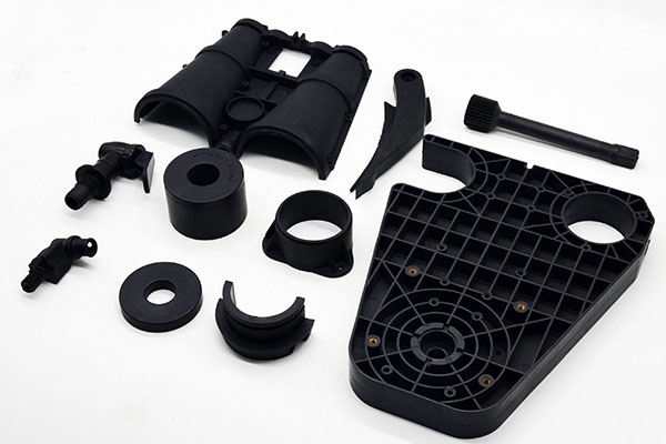
Successful plastic mold molding depends on mastering a series of critical, interconnected details—from intelligent mold design and precise temperature control to selecting the right material and machine—all of which directly determine part quality, production efficiency, and total cost.
The process of plastic mold molding, commonly known as injection molding, is far more complex than simply melting plastic and injecting it into a cavity. It is a precise engineering discipline where seemingly minor details in mold design, process parameters, and material behavior have outsized impacts on the final product. For product designers, engineers, and manufacturers, overlooking these details can lead to defective parts, costly mold rework, and failed production runs. This comprehensive guide moves beyond basic theory to focus on the practical, actionable details you must pay attention to. We will explore the nuances of the injection cycle, dissect common plastic materials, explain the engineering behind molds, and detail how to diagnose and prevent defects. Whether you are new to injection molding or looking to optimize an existing process, this guide will equip you with the essential knowledge to ensure success.
Introduction
Plastic mold molding is a manufacturing process for producing parts by injecting molten plastic material into a precisely machined mold cavity. While the fundamental concept is straightforward, the devil is in the details. Every decision, from the placement of a tiny air vent to the temperature profile of the cooling lines, contributes to the success or failure of a molding project. A well-designed part can be ruined by a poorly engineered mold, and a perfect mold can produce scrap if process parameters are incorrect. This article serves as a detailed checklist for excellence. We will walk through the entire process, highlighting the specific details that require vigilant attention. You will learn not just what to do, but why it matters, with practical insights into material selection, defect analysis, and cost optimization. By the end, you will have a framework for navigating the complexities of plastic molding with confidence.
What Is Plastic Mold Molding?
Plastic mold molding, specifically injection molding, is a cyclical process where thermoplastic or thermoset material is melted, forced (injected) under high pressure into a closed metal mold, cooled until it solidifies, and then ejected as a finished part. The mold (or tool) is the heart of the process—a custom-engineered, often expensive, piece of hardware that defines the part's geometry, surface finish, and dimensional accuracy.
The process is characterized by its:
- High Repeatability: Once established, the process can produce millions of identical parts.
- Complex Geometry Capability: Can create intricate features, threads, and undercuts in a single operation.
- Excellent Surface Finish: Parts can have a ready-to-use finish straight from the mold.
- High Initial Investment: The cost and lead time for mold fabrication are significant, making the process economically viable primarily for medium to high-volume production.
How Does the Injection Cycle Work?
Understanding the cycle is key to controlling quality. Each phase has critical control parameters.
- Clamping: The two halves of the mold are hydraulically or electrically closed and held under immense force (clamp tonnage) to resist the injection pressure. Detail: Insufficient clamp force causes flash—thin webs of plastic leaking out at the mold parting line.
- Injection: Plastic pellets are fed from a hopper into a heated barrel. A rotating screw moves the material forward, melting it through shear and heat. The screw then acts as a plunger, injecting the molten plastic into the mold cavity. Details: Injection speed and pressure must be balanced. Too fast can cause jetting or burn marks; too slow can lead to incomplete filling (short shots).
- Packing & Holding: Additional plastic is packed into the cavity to compensate for material shrinkage as it cools. Detail: This phase is critical for preventing sink marks over thick sections and ensuring dimensional stability.
- Cooling: The part solidifies in the mold. Cooling channels circulate water or oil to remove heat. Detail: Cooling time typically accounts for over 50% of the total cycle time. Uneven cooling causes warpage and internal stresses.
- Ejection: Once sufficiently solid, the mold opens, and ejector pins push the part out. Detail: Ejector pins must be positioned on robust features to avoid part damage or distortion.
Which Thermoplastics Are Most Common?
Material selection is the first major decision, impacting every subsequent detail.
| Material | Key Properties | Shrinkage Rate (Typical) | Critical Processing Detail |
|---|---|---|---|
| Polypropylene (PP) | Tough, flexible, chemical resistant, low cost. | 1.5-2.5% | Prone to warpage; requires uniform cooling and adequate draft angles. |
| Acrylonitrile Butadiene Styrene (ABS) | Good impact strength, rigidity, glossy finish. | 0.4-0.7% | Hygroscopic (absorbs moisture); must be thoroughly dried before processing to prevent splay marks. |
| Polycarbonate (PC) | High impact strength, transparent, heat resistant. | 0.5-0.7% | Very hygroscopic and sensitive to heat history. Requires high drying temperatures and precise melt temperature control. |
| Nylon (PA 6, PA 66) | Strong, wear-resistant, good chemical resistance. | 0.7-1.5% | Extremely hygroscopic. Moisture causes molecular degradation, leading to brittle parts. Drying is non-negotiable. |
| Polyethylene (HDPE, LDPE) | Flexible, chemical resistant, low cost. | 1.5-4.0% | High shrinkage; requires sufficient packing pressure and longer cooling times. |
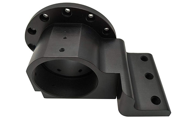
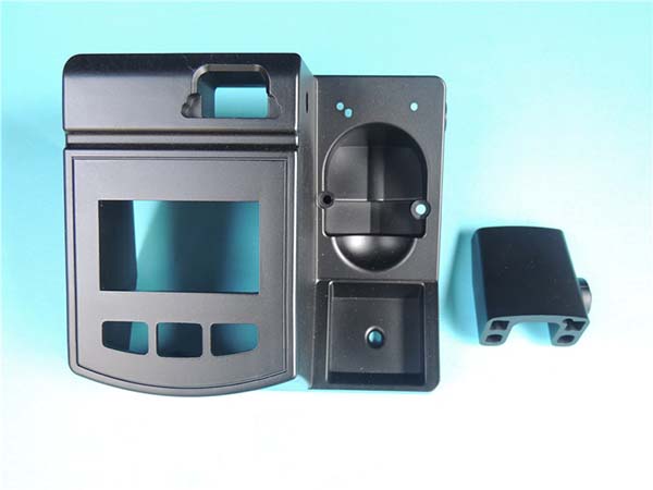
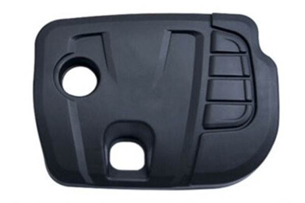
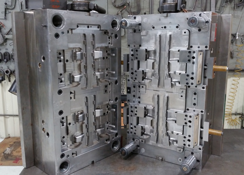
Mold Design Basics: Cavities, Runners, Gates
The mold's design dictates part quality and manufacturability.
- Cavities: The hollow spaces that form the part. Detail: The number of cavities (single vs. multi-cavity molds) directly impacts production rate and tooling cost. All cavities must be balanced to fill uniformly.
- Runners: Channels that deliver molten plastic from the machine nozzle to the cavities.
- Cold Runners: Solidify with the part and are ejected as waste. Simpler mold design.
- Hot Runners: Heated system keeps plastic molten in the channels, eliminating waste and improving cycle time. Detail: Hot runner systems are more complex and expensive but are standard for high-volume production.
- Gates: The small opening where plastic enters the cavity from the runner.
- Gate Location: Perhaps the most critical detail in mold design. It influences fill pattern, weld line location, packing efficiency, and ease of gate removal (vestige). Gates should be placed at the thickest section.
- Gate Type: Edge, submarine, or pin gates are common. For aesthetic parts, hot tip gates or valve gates leave minimal marks.
How to Control Temperature and Pressure?
Process stability hinges on precise control of these variables.
Temperature Control:
- Melt Temperature: Specific to each material (e.g., ABS ~210-240°C, PC ~280-320°C). Too low causes poor flow; too high degrades the polymer.
- Mold Temperature: Controlled via cooling channels. Detail: A difference of just 10°C between mold halves can cause part warpage. Conformal cooling channels, 3D-printed to follow the cavity contour, provide the most uniform cooling.
Pressure Control:
- Injection Pressure: Overcomes the plastic's viscosity to fill the cavity. Typically 500 - 2,000+ psi.
- Holding/Packing Pressure: Usually 50-70% of injection pressure. Applied after cavity is ~95% full to pack in more material and compensate for shrinkage. Detail: Insufficient packing is a primary cause of sink marks and dimensional variation.
What Defects Can Occur and Why?
Identifying and solving defects requires attention to root causes.
| Defect | Visual Description | Primary Causes & Corrective Details |
|---|---|---|
| Sink Marks | Depression or dimple on surface, often over ribs or thick sections. | Cause: Insufficient packing pressure/time; local area cools too slowly. Fix: Increase pack pressure/time; redesign part for uniform wall thickness (rib ≤ 60% of main wall). |
| Warpage | Twisted or bent part, not flat. | Cause: Non-uniform cooling or differential shrinkage. Fix: Optimize cooling channel layout/balance; ensure uniform wall thickness; adjust mold temperatures. |
| Short Shot | Incomplete filling of the mold cavity. | Cause: Insufficient material, low injection speed/pressure, or blocked vent. Fix: Increase shot size, speed, or pressure; check and clear vents. |
| Flash | Thin layer of plastic on the parting line or around ejector pins. | Cause: Excessive injection pressure or insufficient clamp force; mold wear/damage. Fix: Reduce injection pressure; increase clamp tonnage; repair mold. |
| Weld/Knit Lines | Visible line where molten plastic flows meet. | Cause: Inevitable with multiple gates or flow around holes. Fix: Optimize gate location to move line to non-critical area; increase melt/mold temperature. |
| Jetting | Wavy surface pattern near the gate. | Cause: Plastic "shoots" into cavity too fast and cools before filling properly. Fix: Reduce initial injection speed; enlarge gate size. |
Cost Factors: Tooling, Material, Labor
Understanding cost drivers helps in budgeting and decision-making.
- Tooling (Mold) Cost: The largest upfront investment. Driven by:
- Part Complexity: Size, number of undercuts, surface finish (polished vs. textured), and required tolerances.
- Mold Material & Construction: Number of cavities, use of hardened steels (for longevity), and advanced systems (hot runners, side-actions, lifters).
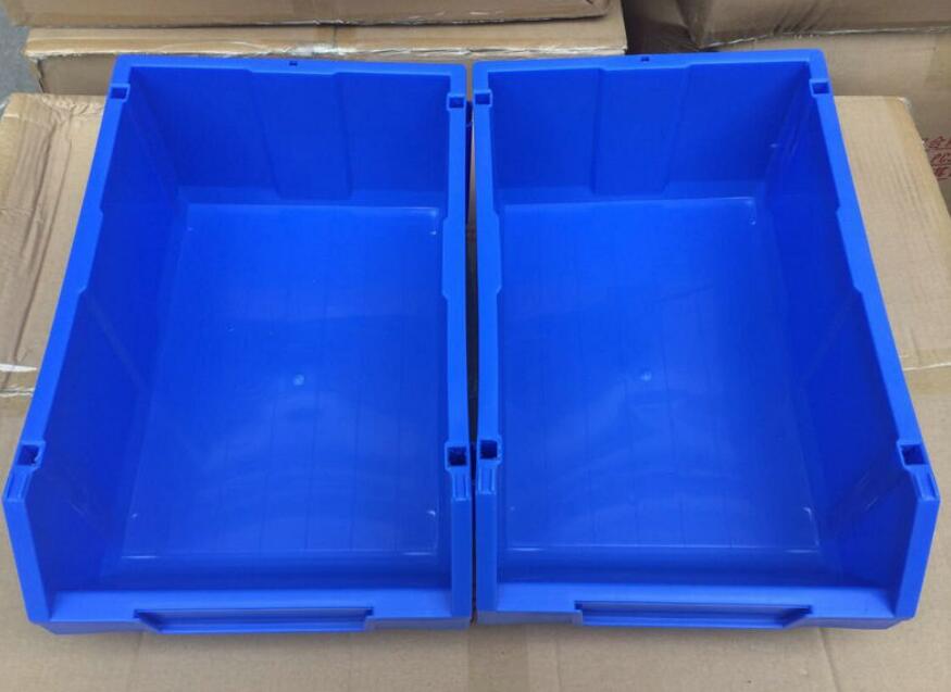
- A simple single-cavity aluminum prototype mold may cost $3,000-$10,000, while a multi-cavity production steel mold can exceed $100,000.
- Material Cost: Determined by part weight and material price per kilogram. Minimizing part weight through good design is a direct cost-saving measure.
- Cycle Time & Labor: The time to produce one part dictates machine utilization cost. Detail: Reducing cooling time by 2 seconds on a high-volume job saves tens of thousands of dollars annually. Automated part removal reduces labor cost.
How to Choose the Right Machine Size?
Selecting a machine with the correct capacity is essential for quality and efficiency.
- Clamp Tonnage: Must be sufficient to keep the mold closed against injection pressure. A general rule: Required Tonnage = Projected Part Area (in²) x Injection Pressure (psi) / 2000. Always add a 10-20% safety factor.
- Shot Size: The machine must be able to inject enough plastic to fill the mold (part + runners). The part(s) should typically use 20-80% of the machine's maximum shot capacity for optimal control.
- Example: A part with a projected area of 50 in², molded at 1000 psi injection pressure, requires at least 25 tons of clamp force (50 * 1000 / 2000). A 30-50 ton machine would be appropriate.
Conclusion
Mastering plastic mold molding requires a meticulous, detail-oriented approach that spans the entire product lifecycle—from the initial material selection and part design to the intricacies of mold engineering and process parameter tuning. By paying close attention to the gate location, cooling uniformity, pressure profiles, and material drying, you can prevent the vast majority of defects and ensure a stable, cost-effective production process. Remember, the mold is a long-term investment, and time spent on Design for Manufacturability (DFM) analysis with your molding partner is the single most effective way to avoid costly mistakes. Treating injection molding as a partnership between design, tooling, and production engineering is the surest path to manufacturing high-quality plastic parts consistently and efficiently.
Frequently Asked Questions (FAQ)
What is the most important rule for designing a part for injection molding?
Maintain uniform wall thickness. This is the golden rule. Variations in wall thickness cause differential cooling and shrinkage, leading directly to defects like sink marks, warpage, and internal stresses. If thickness must change, use a gradual transition (over a distance of 3x the thickness change).
Why is "draft" so critical in mold design?
Draft is a slight taper (usually 1-3 degrees per side) applied to walls parallel to the mold opening direction. It is essential for part ejection. Without sufficient draft, the part will scrape and gall against the mold steel during ejection, causing damage, wear, and increasing required ejection force. Deep textures require additional draft (often 1° plus 1° per 0.001" of texture depth).
How long does it take to build a typical injection mold?
Lead time varies dramatically with complexity. A simple single-cavity prototype mold in aluminum: 3-5 weeks. A multi-cavity production mold in hardened steel with hot runners and complex actions: 12-20 weeks. This timeline includes design, machining, fitting, polishing, and sampling/trial.
Can different colored plastics be used in the same mold?
Yes, but with a crucial detail: Thorough purging is required when switching colors or materials. Purging compound is used to clean out the previous material from the machine barrel and screw. Switching from a light to a dark color is easier than dark to light. Switching between incompatible materials (e.g., ABS to Nylon) requires extremely thorough purging to prevent contamination and part failure.
Contact Yigu Technology for Custom Manufacturing.
At Yigu Technology, we understand that success in plastic mold molding is built on getting the details right. We partner with you from the earliest design stage, providing in-depth Design for Manufacturability (DFM) analysis to optimize your part for quality, performance, and cost-effective molding.
Our expertise covers the full spectrum: material selection, precision mold design and fabrication, process development, and high-volume production. We leverage advanced technologies like mold flow simulation and conformal cooling to solve complex challenges before steel is cut.
Don't leave the critical details of your next plastic molding project to chance. Contact Yigu Technology today for a comprehensive project review and consultation. Let us help you turn your design into a flawlessly manufactured reality.