Introduction
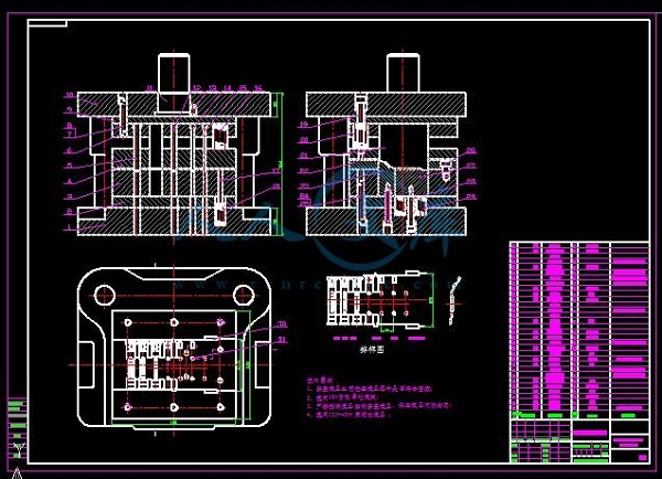
In the realm of mold design and manufacturing, the mold general assembly drawing serves as a fundamental and crucial element. It is not merely a drawing but a comprehensive visual and technical representation that encapsulates all the necessary information for the successful production of molds. This drawing serves as a communication tool between designers, manufacturers, and other stakeholders involved in the mold - making process.
A well - crafted mold general assembly drawing (mold assembly drawing) can significantly enhance the efficiency and accuracy of mold production. It provides a clear overview of how all the individual components of a mold fit together, their relative positions, and how they function in unison. For instance, in plastic injection molding, the mold general assembly drawing will show the core and cavity parts, the gating system, the cooling channels, and the ejection mechanism. Each of these elements is critical to the proper functioning of the mold, and their correct representation in the drawing is essential.
Without a detailed and accurate mold general assembly drawing, misunderstandings can occur during the manufacturing process. Parts may not fit together correctly, leading to costly rework, delays in production, and potentially, a lower - quality final product. Therefore, understanding the technical requirements of a mold general assembly drawing is of utmost importance for anyone involved in the mold - making industry. In the following sections, we will delve deep into these technical requirements from various aspects to help you create or interpret these drawings effectively.
Key Elements in a Mold General Assembly Drawing
Dimensions and Tolerances
Dimensions are the most basic yet crucial aspect of a mold general assembly drawing. Every part of the mold, from the smallest pin to the largest plate, must have its dimensions accurately marked. Precise dimensions ensure that each component can be manufactured to the correct size and fit together perfectly during assembly. For example, in a mold for manufacturing small electronic components, the dimensions of the cavity where the component is formed need to be within a very small tolerance range. A deviation of even a few tenths of a millimeter can lead to the produced components not meeting the required specifications.
Tolerances define the acceptable range of variation for each dimension. There are different tolerance systems used in the mold - making industry, such as the ISO (International Organization for Standardization) tolerance system and the ANSI (American National Standards Institute) tolerance system. Common tolerance notations include unilateral tolerances (e.g., +0.05/-0), bilateral tolerances (e.g., ±0.03), and limit dimensions (e.g., minimum size 10.00 and maximum size 10.05). A tight tolerance, like ±0.01mm, is often required for high - precision molds, such as those used in optical lens manufacturing. Tighter tolerances increase the manufacturing cost but are essential for ensuring the functionality and quality of the final product. On the other hand, looser tolerances can be acceptable for less critical components or in some cases where cost - savings are a priority, but they must still be carefully determined to avoid issues in assembly and product performance.
Part Identification
Clear part identification is vital in a mold general assembly drawing. Each individual part of the mold should be uniquely identified. This is usually done through a combination of numbering and annotations.
- Numbering: A sequential numbering system is often used, where each part is assigned a distinct number. For example, in a complex injection mold with dozens of parts, the core might be numbered as part 1, the cavity as part 2, and each individual ejector pin as part 3 - 1, part 3 - 2, etc. This numbering system allows for easy reference during the manufacturing, assembly, and maintenance processes.
- Annotations: In addition to numbers, parts are often accompanied by annotations that describe their function, material, and any special features. For instance, an annotation might state “Part 5: Guide Pin, Material: Hardened Steel, Diameter: 10mm, Length: 50mm”. This information helps the manufacturing team to understand the requirements for each part and select the appropriate materials and manufacturing processes.
Proper part identification simplifies the process of ordering replacement parts in case of damage during the mold's lifespan. It also speeds up the assembly process as workers can quickly identify and locate the correct parts.
Assembly Instructions
Assembly instructions are another key element in a mold general assembly drawing. These instructions provide guidance on how to assemble the mold correctly. They can be presented in several ways:
- Arrows: Arrows are commonly used to indicate the direction of movement during assembly. For example, an arrow might show the direction in which a slide plate should be inserted into the mold base. Multiple arrows can be used to show the sequential movement of parts.
- Step - by - step text instructions: These are detailed written instructions that describe each step of the assembly process. For example, “Step 1: Insert the guide pins into the guide pin bushings in the mold base. Ensure a tight fit.” “Step 2: Place the cavity plate onto the mold base, aligning the holes with the guide pins.” Such text instructions are especially useful for complex molds with many parts and intricate assembly sequences.
- Exploded views: An exploded view is a visual representation where the parts of the mold are shown separated from each other but in their relative positions as if they were about to be assembled. This gives the assembler a clear overview of how the parts fit together and the order in which they should be assembled.
Clear and accurate assembly instructions reduce the risk of incorrect assembly, which can lead to mold malfunction, premature wear, and costly rework.
Technical Requirements from Different Perspectives
Material Specifications
The choice of materials in mold manufacturing is critical, as different materials have distinct properties that significantly impact the performance and lifespan of the mold. Here are some commonly used mold materials and their characteristics presented in a table:
| Material | Hardness | Wear Resistance | Heat Resistance | Cost | Application Scenarios |
| P20 Steel | Medium (30 - 35 HRC when pre - hardened) | Medium, suitable for common engineering plastics | Moderate, can work in normal temperature environments | Relatively low | Used for molds of common plastic products like ABS, PP, PE products with medium - low complexity and small - to - medium batch production, such as toy shells, simple plastic parts. |
| 718H Steel | Higher (35 - 40 HRC when pre - hardened) | Better than P20, suitable for filled engineering plastics | Good, can handle slightly higher - temperature processing | Moderate | Ideal for high - precision and long - life molds of high - requirement engineering plastics, like PA + GF, PBT, and for precision electronic components and automotive functional parts molds. |
| NAK80 Steel | High (40 - 42 HRC when pre - hardened) | High, excellent for high - precision and high - gloss applications | Good, suitable for normal plastic processing temperatures | Higher | Used for high - transparency or high - gloss plastic products, such as optical components, cosmetic packaging, and automotive high - gloss parts. |
| H13 Steel | High (48 - 52 HRC after heat treatment) | Medium, can be improved by surface treatment | Excellent, can work at 500 - 600°C for a long time and withstand up to 650°C short - term | High | Applied to molds for high - temperature engineering plastics like PEEK, PEI, LCP, and for molds with high - stress and high - temperature cycling requirements. |
For example, if a mold is used to produce plastic products with high precision requirements, such as optical lenses, NAK80 steel may be a better choice due to its high hardness, excellent polishing performance, and good dimensional stability. On the other hand, for large - scale production of common plastic products with lower precision requirements, P20 steel can meet the needs with its relatively low cost and moderate performance.
Surface Finish Requirements
The surface finish of a mold is crucial as it directly affects the surface quality of the molded products. Different surface roughness requirements are applicable in various scenarios:
- Mirror Finish (Ra ≤ 0.01 - 0.05μm): This is required for molds used to produce optical components like lenses, transparent plastic products such as cosmetic packaging, and high - gloss automotive parts. A mirror - like surface finish ensures that the molded products have high light transmittance and a smooth, shiny appearance. For example, in the production of camera lens molds, a mirror - finish surface is essential to prevent light scattering and ensure high - quality imaging.
- Semi - Gloss Finish (Ra = 0.05 - 0.8μm): Molds for producing consumer electronics housings, some household appliances, and toys often require a semi - gloss finish. This finish gives the products a relatively smooth surface while being more cost - effective to produce compared to a mirror finish. For instance, the molds for mobile phone housings usually have a semi - gloss surface finish to provide an aesthetically pleasing appearance.
- Rough Surface Finish (Ra = 1.6 - 12.5μm or higher): In some cases, a rough surface is desired. For example, in molds for producing parts that need to have good adhesion with other materials, such as parts that will be coated or bonded later. Also, for molds used in the production of certain industrial parts where appearance is not the primary concern, a rough surface finish can be acceptable. In the manufacturing of large - scale mechanical parts' molds, a relatively rough surface finish may be used as long as it does not affect the functionality of the final product.
Mechanical Properties
Mechanical properties such as hardness, strength, and toughness are vital for molds, and they are clearly indicated and specified on the mold general assembly drawing.
- Hardness: Hardness is a measure of a material's resistance to indentation or scratching. In the mold general assembly drawing, hardness is usually specified using scales like Rockwell hardness (HRC, HRB, etc.), Brinell hardness (HB), or Vickers hardness (HV). For example, a cold - working mold made of high - carbon steel may have a hardness requirement of 58 - 62 HRC to ensure high wear resistance during the cold - forming process of metals. High - hardness molds can better maintain their shape and dimensional accuracy during the molding process, reducing the risk of deformation.
- Strength: Tensile strength, compressive strength, and shear strength are important mechanical properties for molds. These values are often specified in the drawing as minimum requirements. For example, a mold used for high - pressure die - casting needs to have high tensile and compressive strength to withstand the high - pressure forces exerted by the molten metal during the casting process. The strength requirements ensure that the mold can endure the mechanical stresses without breaking or deforming during operation.
- Toughness: Molds need to have sufficient toughness to resist cracking under impact or cyclic loading. Toughness is related to the ability of the material to absorb energy without fracturing. In the drawing, toughness may not be directly specified by a single value like hardness or strength, but it can be inferred from the choice of material and the overall design of the mold. For example, molds made of alloy steels with appropriate heat treatment are often used to ensure good toughness, especially in applications where the mold is subject to repeated impact, such as in forging dies.
Comparison of Requirements in Different Industries
The technical requirements of mold general assembly drawings can vary significantly across different industries. Let's take a look at the differences in the automotive, electronics, and medical industries through the following table:
| Industry | Precision Requirements | Material Requirements | Surface Finish Requirements | Special Requirements |
| Automotive | High - typically ±0.05 - 0.1mm for critical parts. For example, in engine block molds, dimensional accuracy is crucial for proper engine performance. | High - strength and wear - resistant materials like alloy steels. For instance, H13 steel is commonly used in die - casting molds for automotive parts due to its high - temperature resistance and good mechanical properties. | Semi - gloss to medium - smooth surface finish (Ra = 0.8 - 1.6μm) for most exterior and interior parts. However, for parts with high - aesthetic requirements, a higher - quality finish may be needed. | Molds often need to withstand high - volume production and high - pressure injection or casting processes. They also need to be designed to meet automotive safety and durability standards. |
| Electronics | Ultra - high - often within ±0.01 - 0.03mm, especially for components like connectors and micro - electronic parts. The small size and high - precision nature of electronic components demand extremely accurate molds. | Materials with good electrical insulation and dimensional stability, such as certain grades of P20 steel with modified properties for electronic applications. | High - precision mirror finish (Ra ≤ 0.05μm) for optical components in electronics, and semi - gloss to smooth finish (Ra = 0.05 - 0.8μm) for general plastic housings and components. | Molds must be designed to prevent electrostatic discharge (ESD) and electromagnetic interference (EMI), which could damage sensitive electronic components during the molding process. |
| Medical | High - precision, with tolerances often in the range of ±0.01 - 0.05mm. In medical device molds, precision is critical for the proper fit and function of components, such as syringe molds. | Biocompatible materials like special grades of stainless steel and medical - grade plastics. For example, 316L stainless steel is commonly used in molds for medical implants due to its excellent biocompatibility. | High - quality surface finish, often mirror - like (Ra ≤ 0.05μm) for components that come into contact with the body, to ensure smooth surfaces and prevent cell adhesion and bacterial growth. | Molds need to meet strict medical regulatory standards, such as ISO 13485 for medical device quality management. They also require strict cleaning and sterilization procedures. |
As we can see, each industry has its unique set of requirements for mold general assembly drawings, driven by the specific needs of the products being manufactured. These requirements must be carefully considered during the design and production of molds to ensure high - quality end - products.
Yigu Technology's Perspective
As a non - standard plastic metal products custom Supplier, Yigu Technology deeply understands the significance of strict technical requirements for mold general assembly drawings. With years of experience in the industry, we have always emphasized precision in dimensions, appropriate material selection, and excellent surface finish in our mold manufacturing.
We are proficient in handling various complex mold designs, ensuring that each mold we produce meets the high - standard requirements of different industries. Our team of experts pays close attention to every detail in the mold general assembly drawing, from part identification to assembly instructions, to guarantee seamless production and assembly processes. By strictly adhering to these technical requirements, we can provide our customers with high - quality molds that meet their specific needs and contribute to the success of their products.